Step 1 Powering down
Step 2 Preparing the dashboard
This modification is designed to be installed at Issue 44.
If you’re not at that stage yet, you can test your screens and preview the animations in ‘test mode’ here.
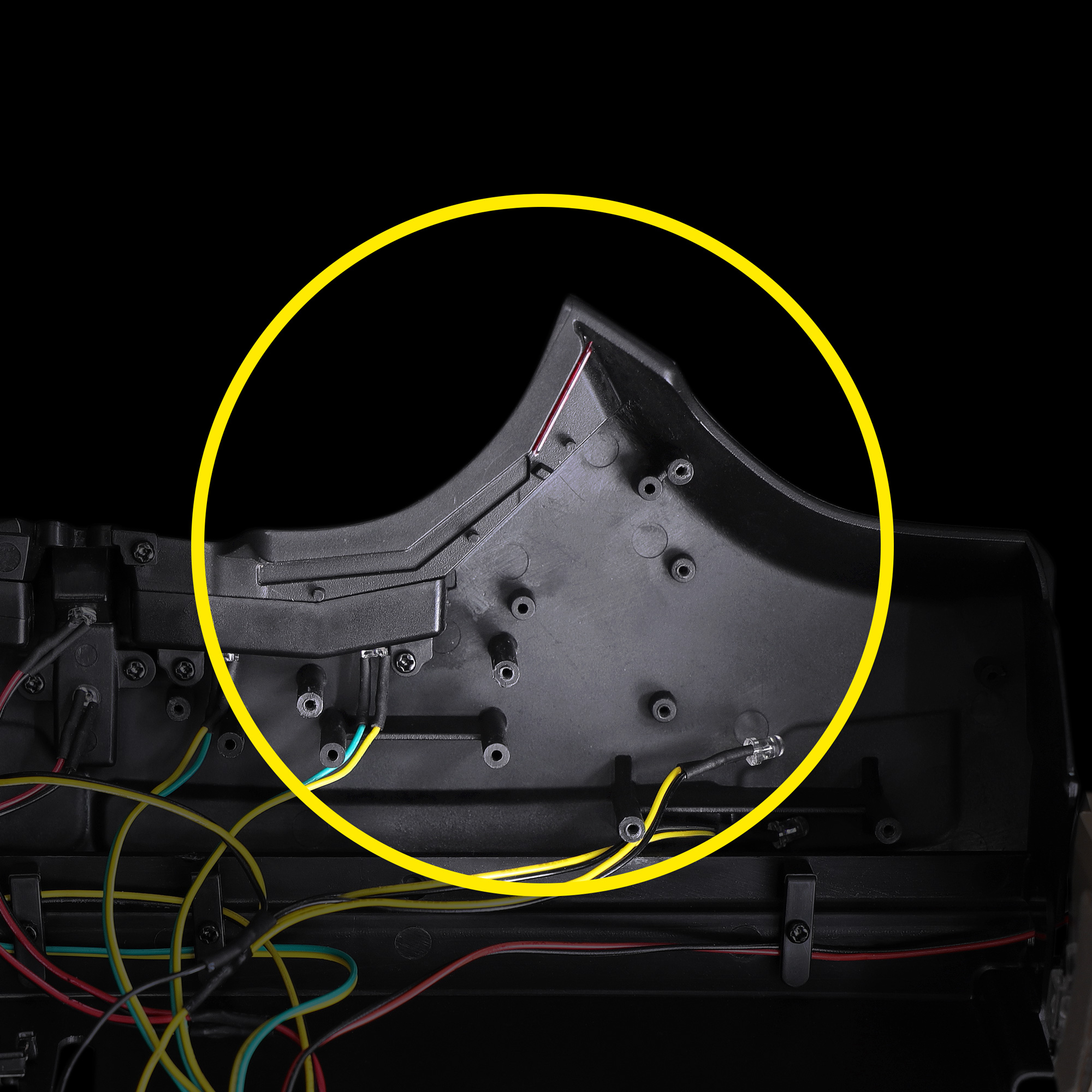
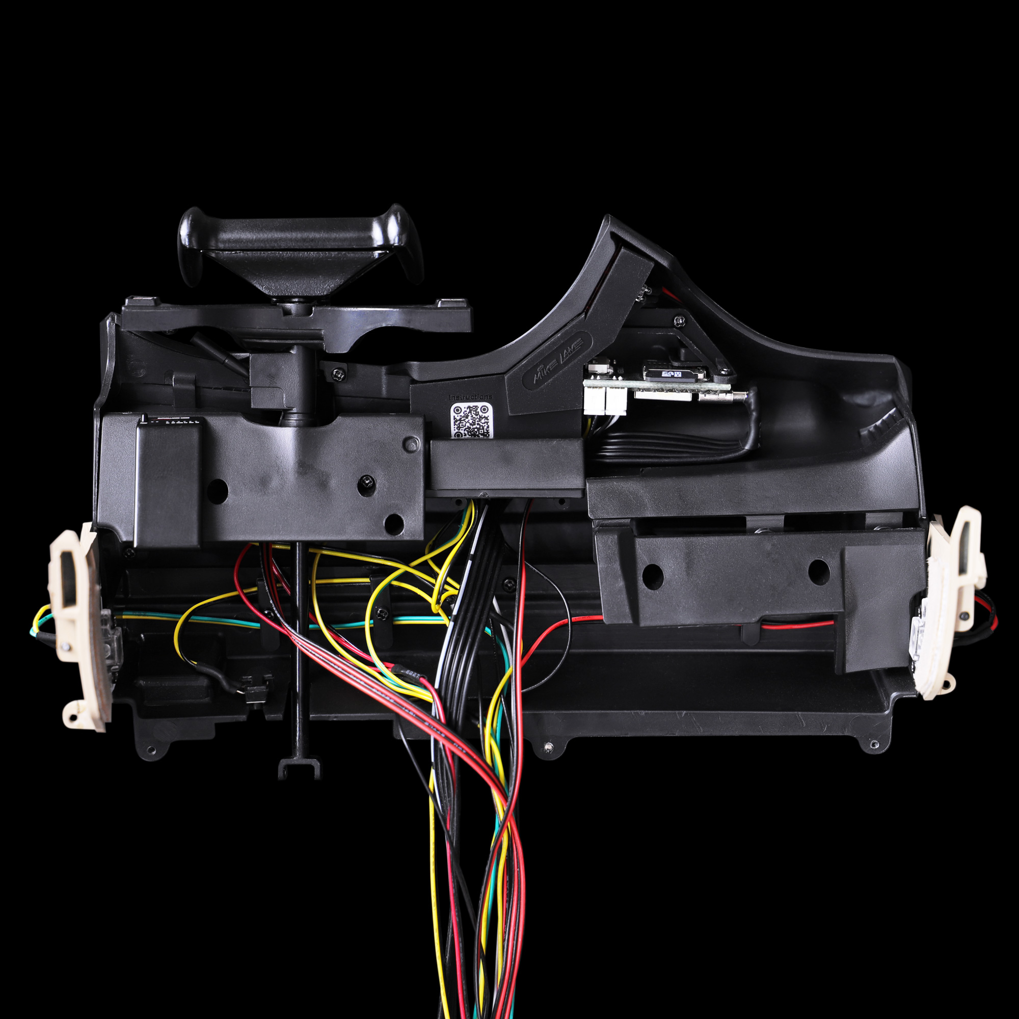
To continue with the full installation, you’ll need to get the underside of your dashboard to this point.
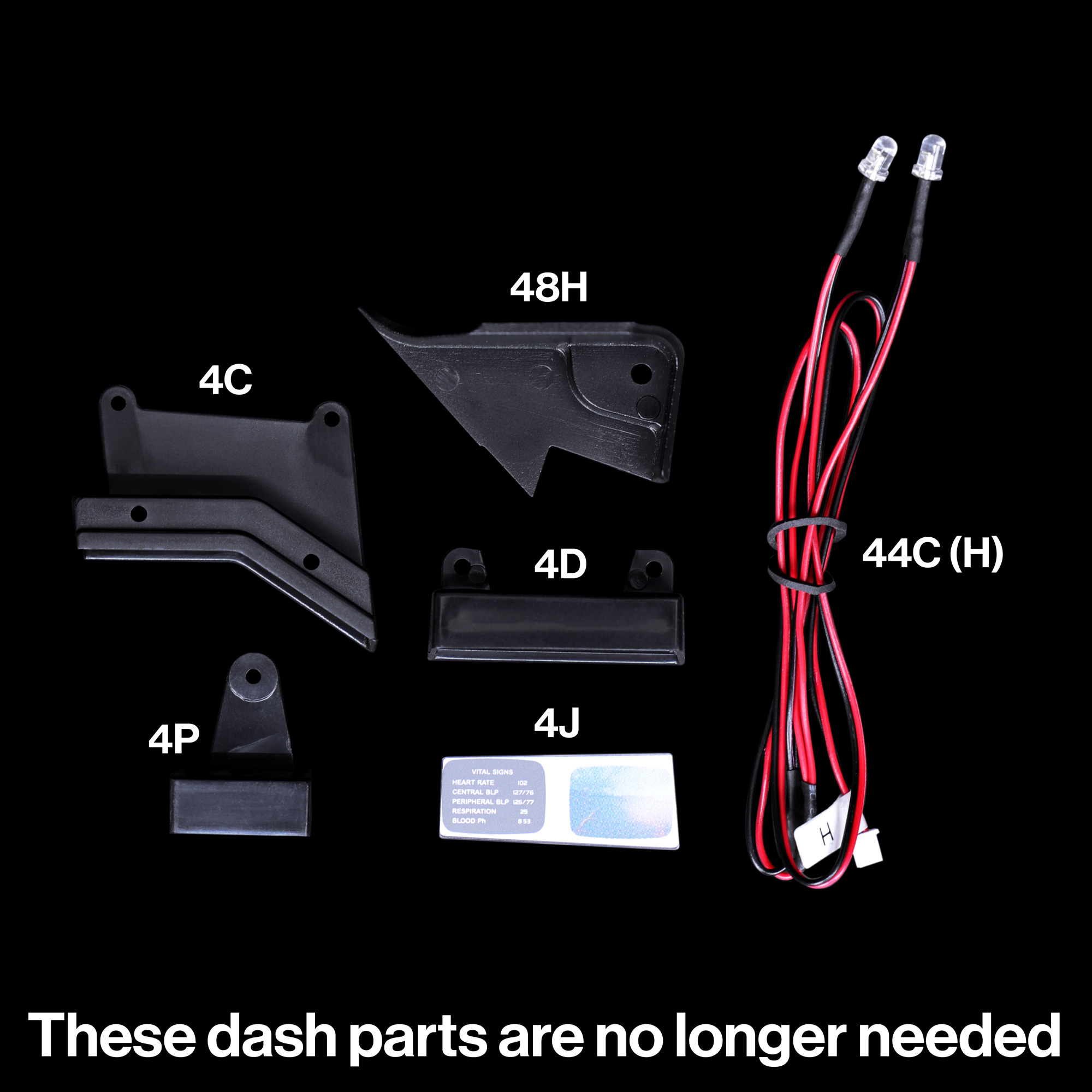
The following parts can be removed from the dashboard and will no longer be needed: 4C, 4D, 4J, 4P, 48H. They will be replaced with the new monitor assembly.
You can continue to install the battery compartment, just don’t connect the battery cable C to the mainboard. For now you can coil the cable inside the battery compartment.
LED cable H (part 44C) from Issue 44 can also be disconnected from the main circuit board and removed as it will no longer be needed.
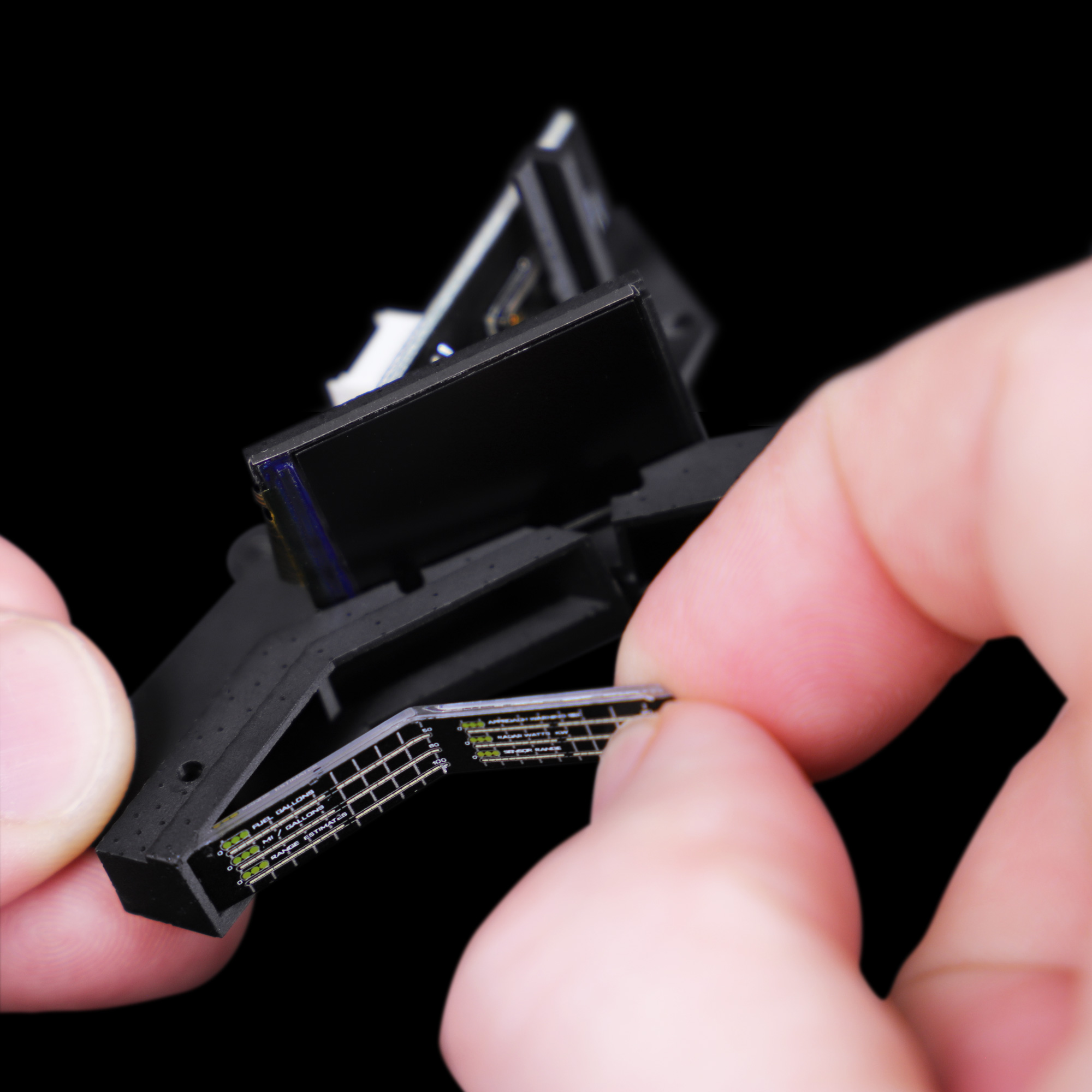
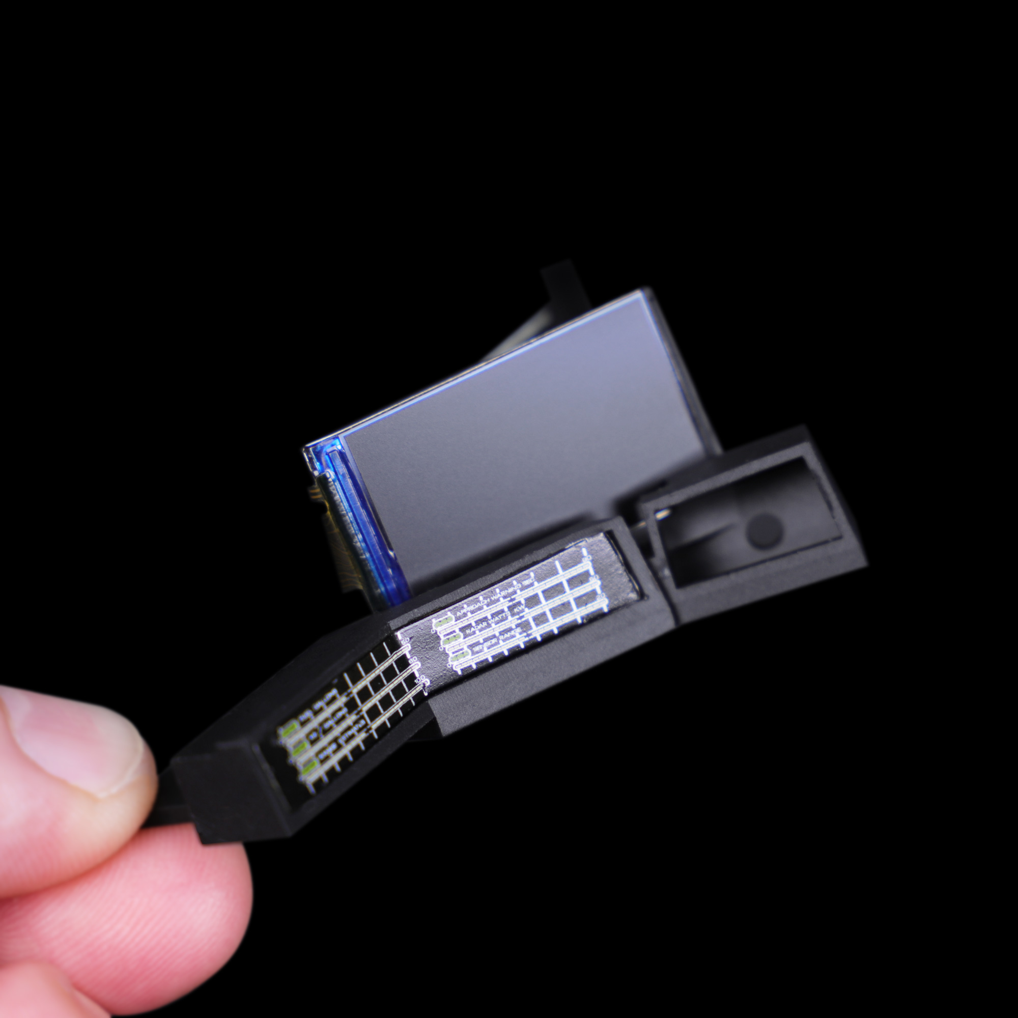
Step 3 Installing the dual monitor bezel
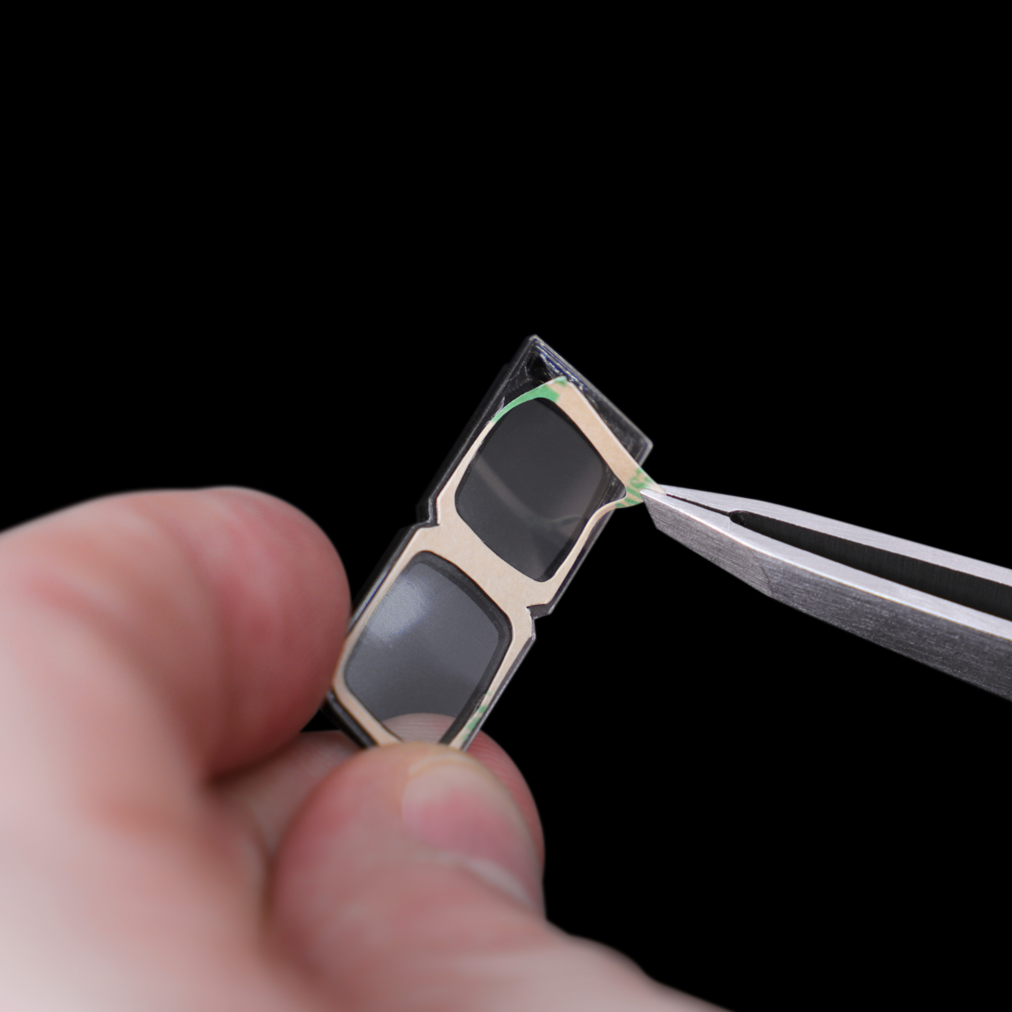
Ensure the lens is clean on both sides before installing.
Using tweezers, remove the 3M backing and install into position, starting at the bottom-right corner of the bezel.
Step 4 Installing the stock dashboard panel
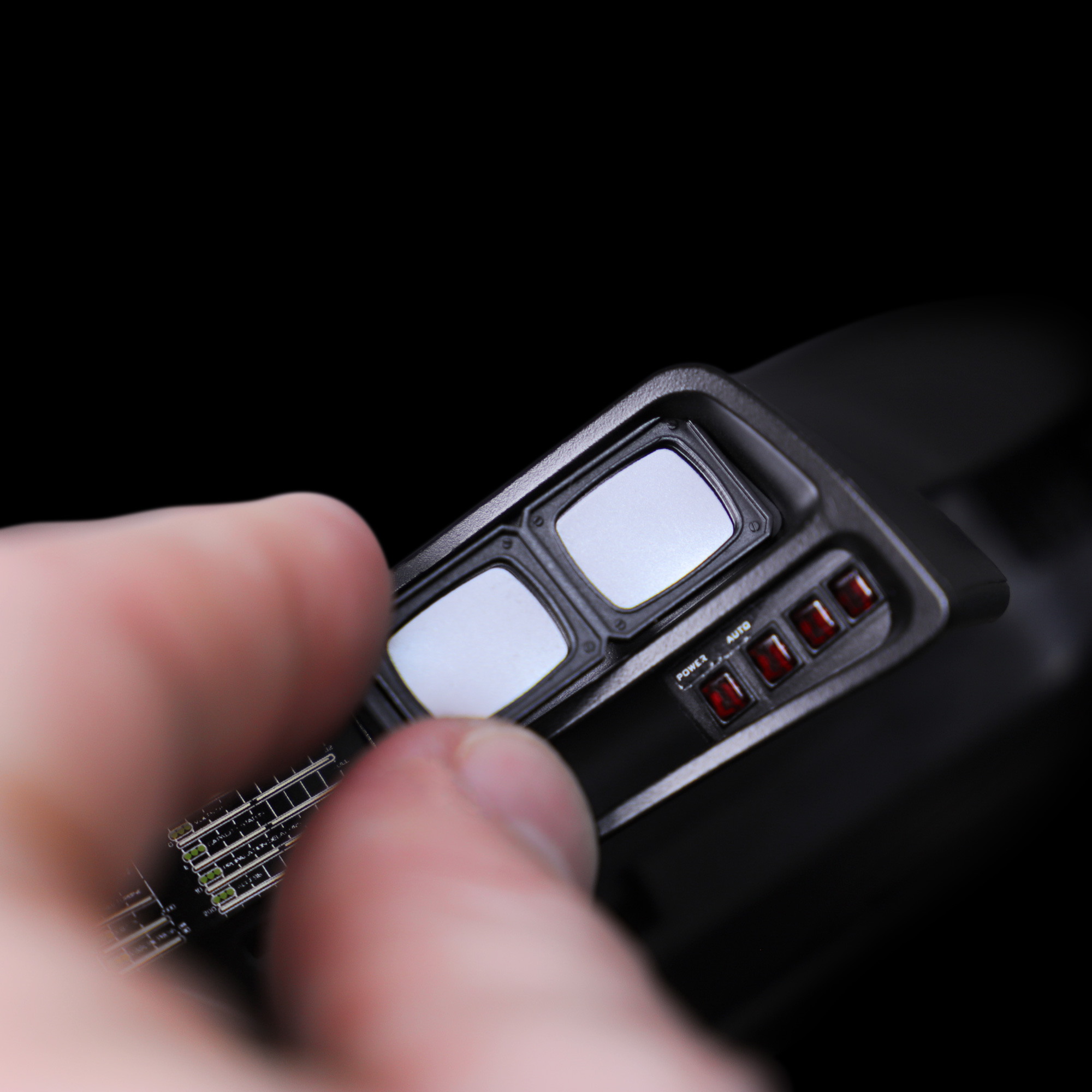
Install the stock dashboard panel (part 4I) from Issue 4 into the new monitor assembly.
When handling the device, take care not to hold or put any pressure on the LCD screen. This is a fragile component and may break if not handled with care.
Step 5 Installing the LED’s
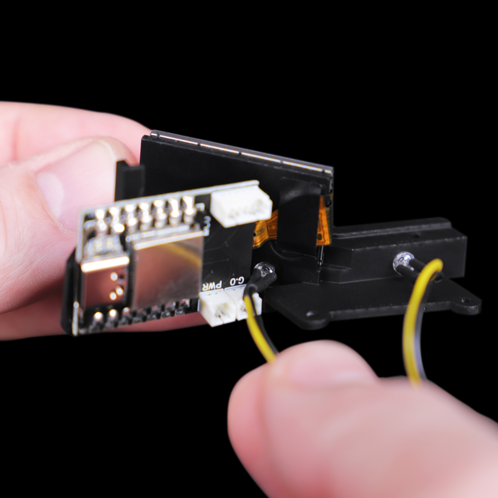
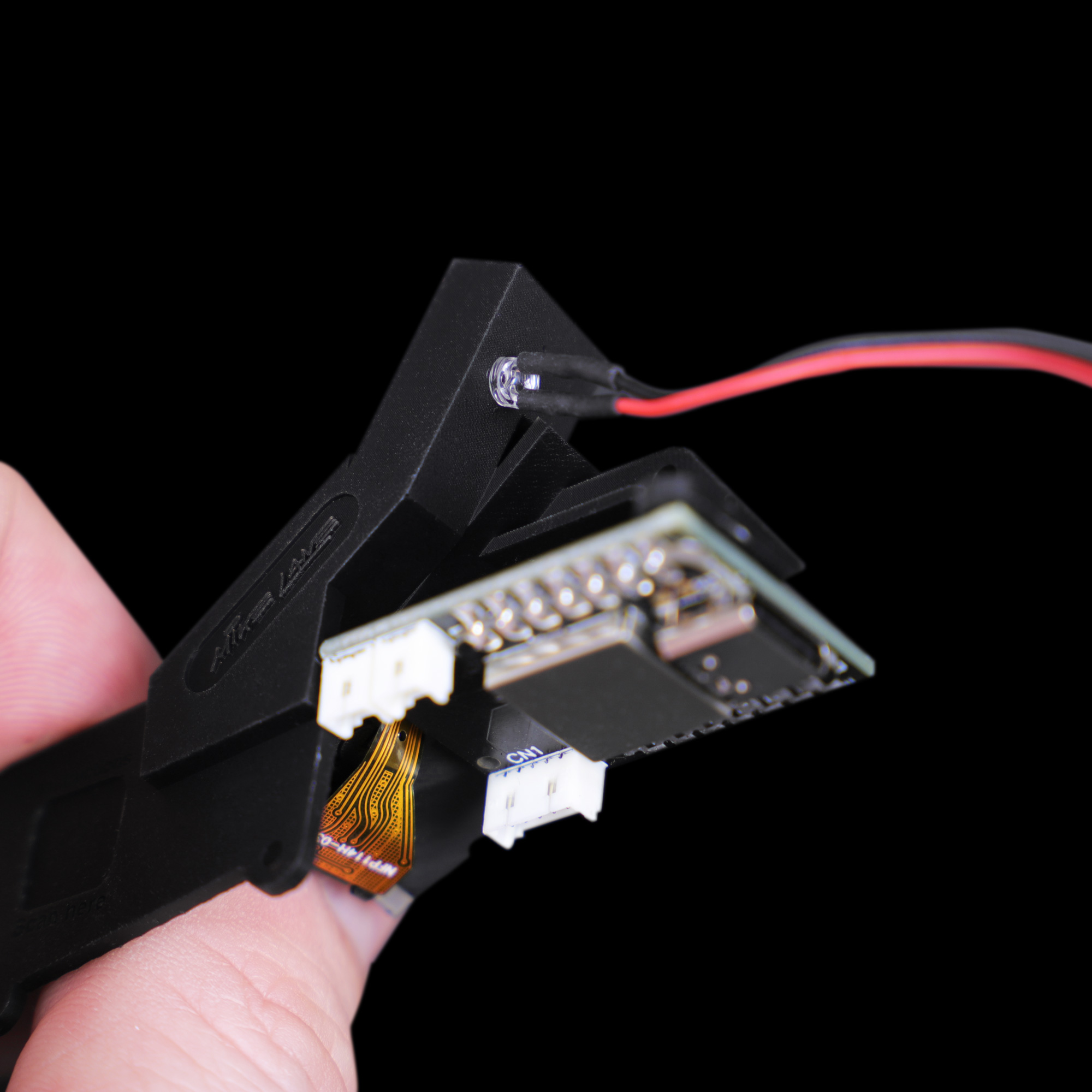
Install the three LED’s from Issue 44 into the rear of the new monitor assembly. You will need part 44E (J) with the yellow cables and part 44B (G) with the red cable.
You will notice that part 44E (J) with the yellow cables has three LED’s. For now, we will only be utilising two of these LED’s. The third LED gets installed into the dash panel to the left of the steering wheel at issue 47.
Step 6 Connecting the cables to the screen controller
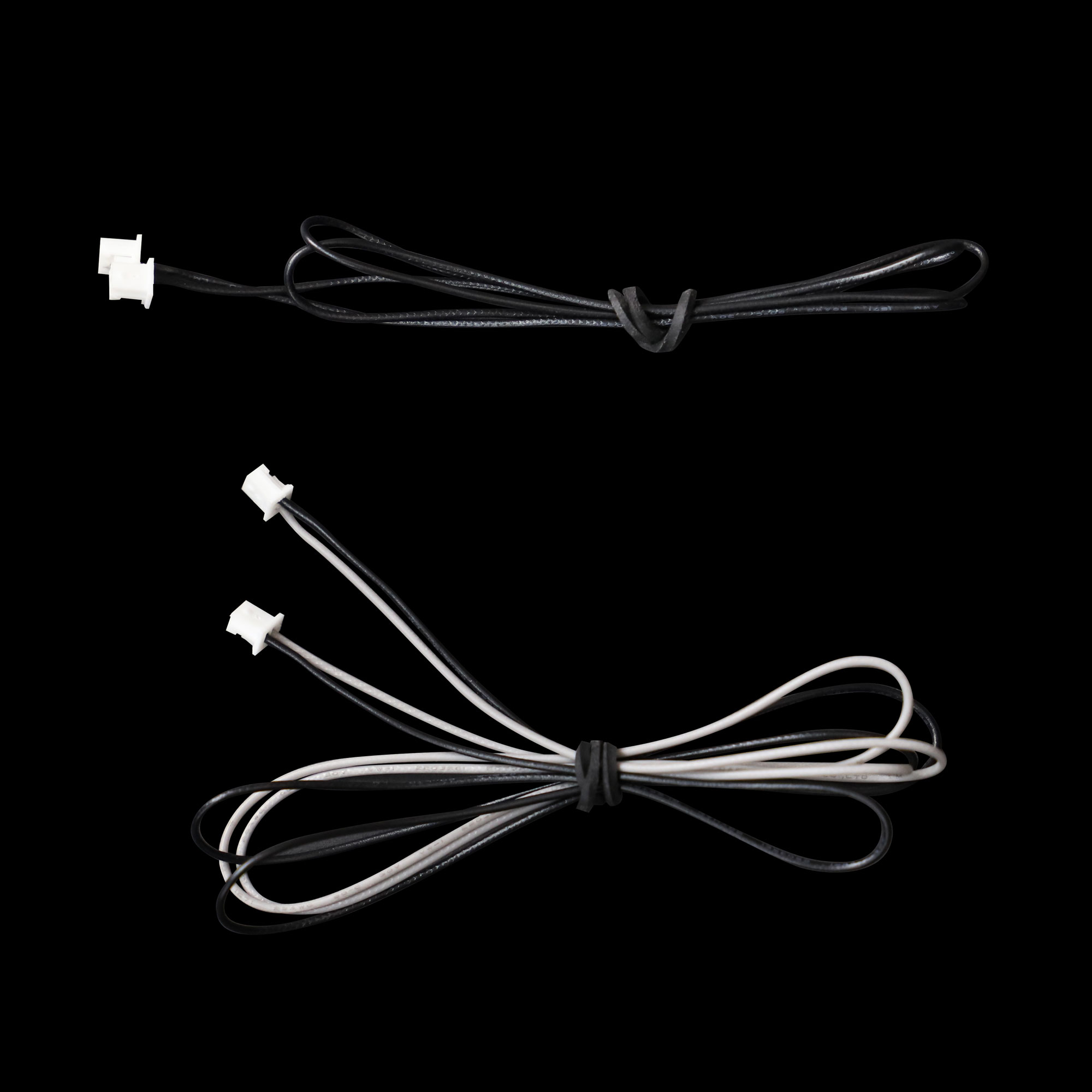
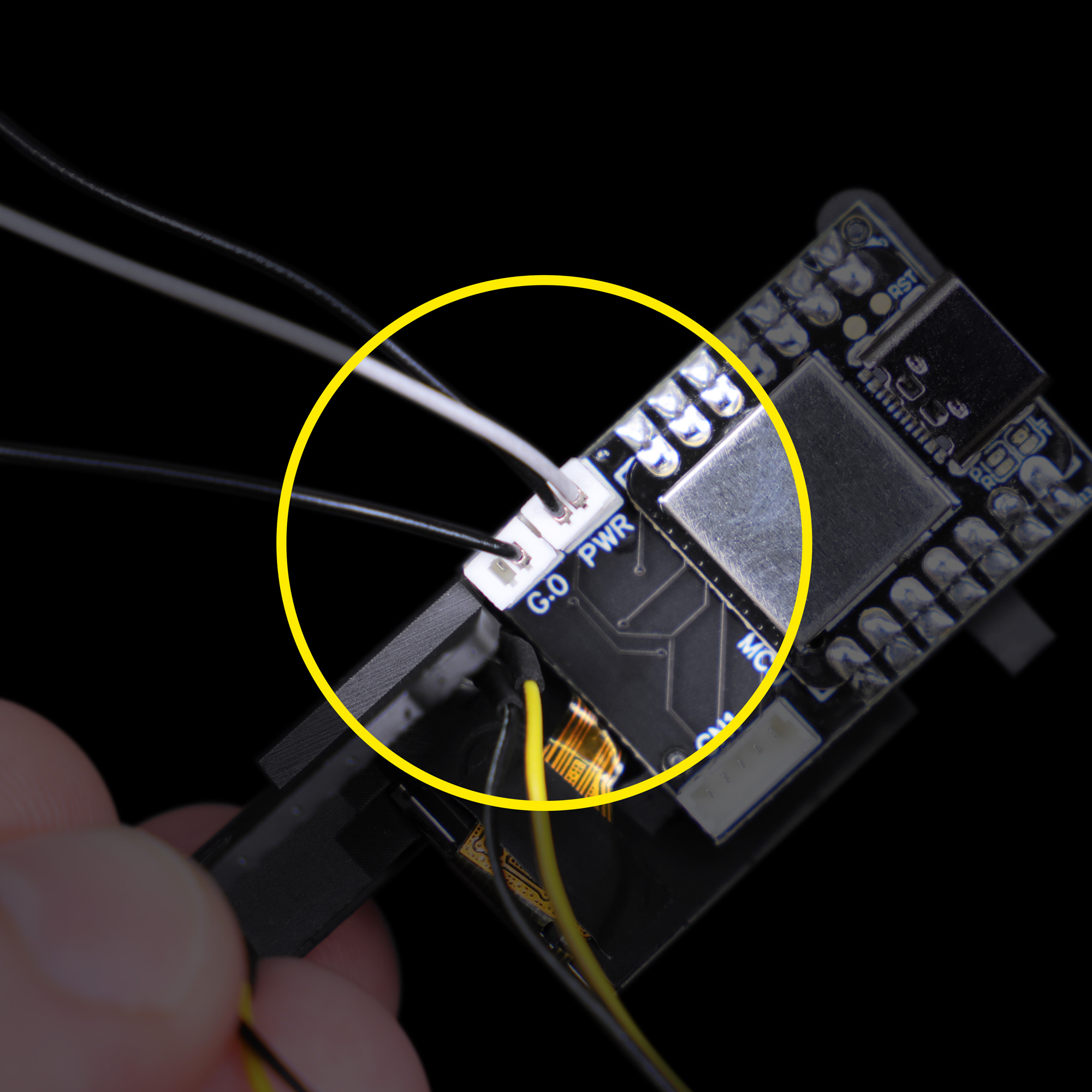
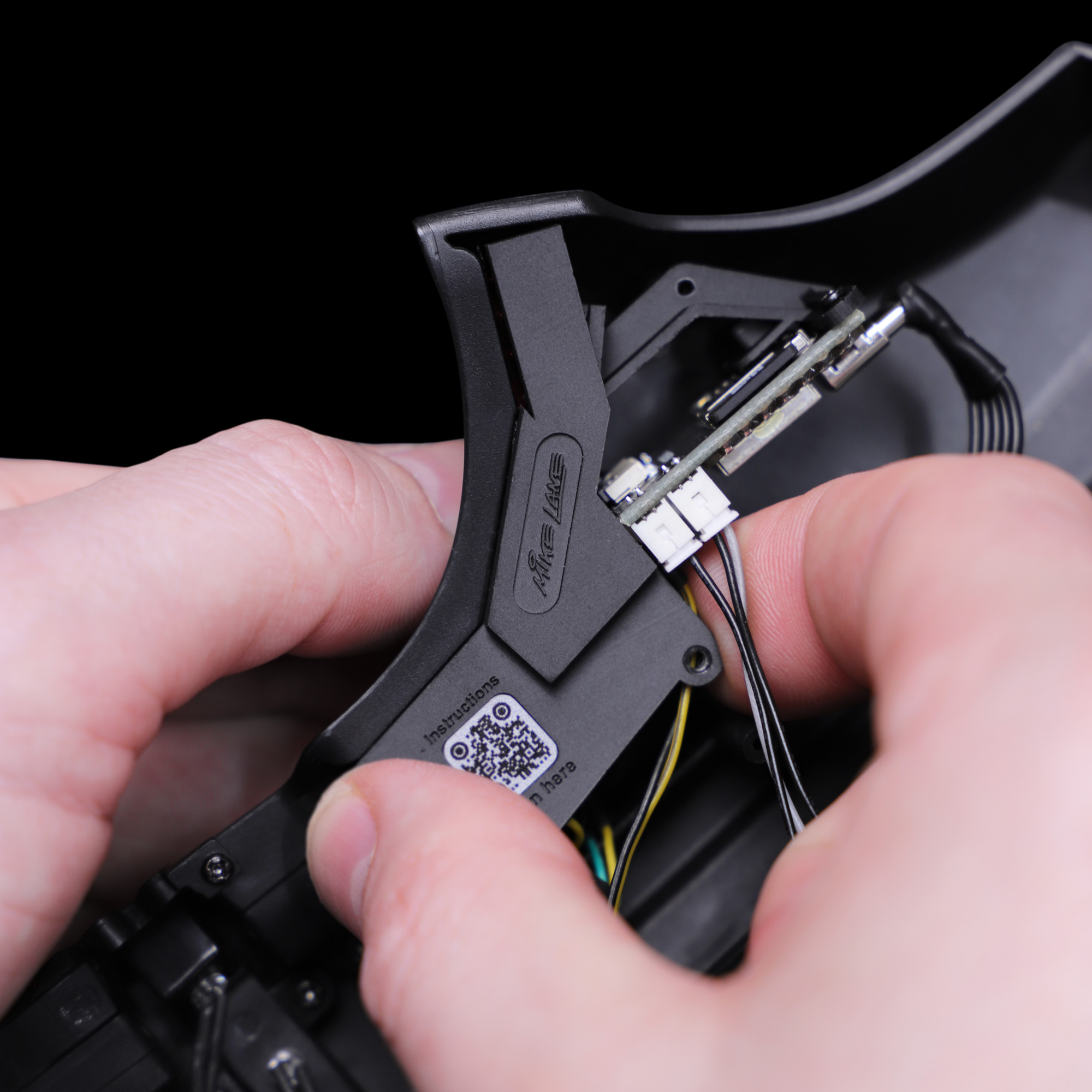
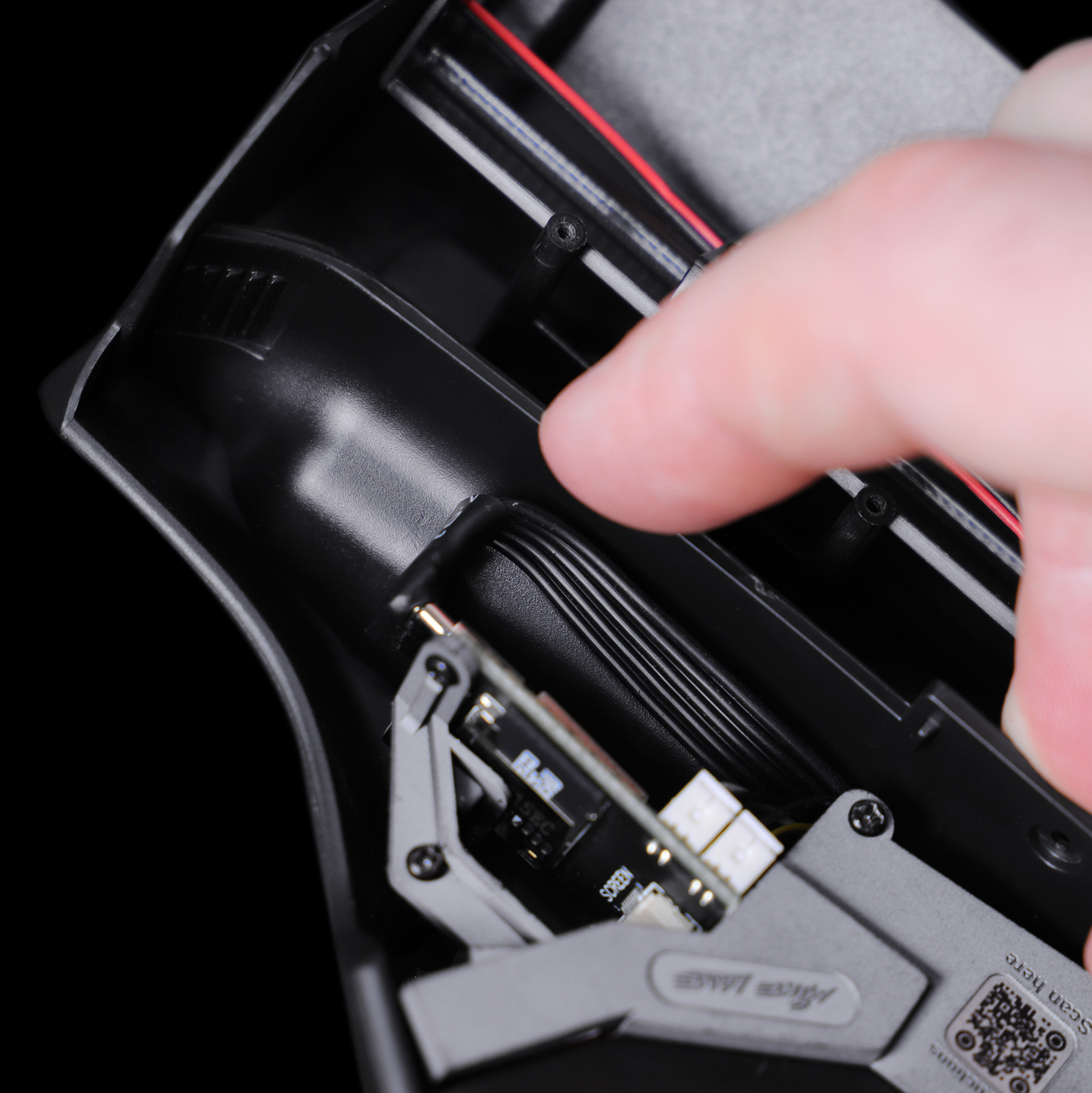
Take the long single black cable provided within this kit and connect to the G.O socket on the screen controller, as pictured.
Take the long black and grey cable provided within this kit and connect to the PWR socket on the screen controller, as pictured.
Ensure that all cable connections match the photos exactly! Connecting the PWR cable to the incorrect socket may damage the circuit board when power is supplied.
Step 7 Installing the USB-C cable (Optional but recommended)
In this configuration, you must ensure that USB power is your models only power source.
Never have batteries or other power mods installed at the same time as powering your model via USB-C.
Power option 1 – USB-C (Recommended)
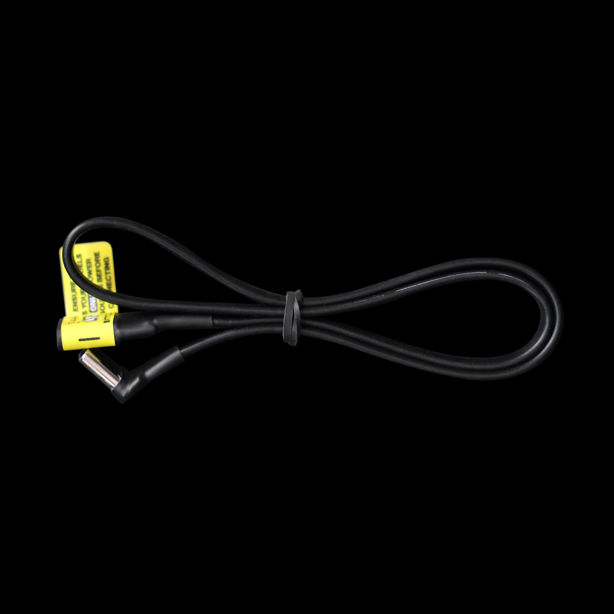
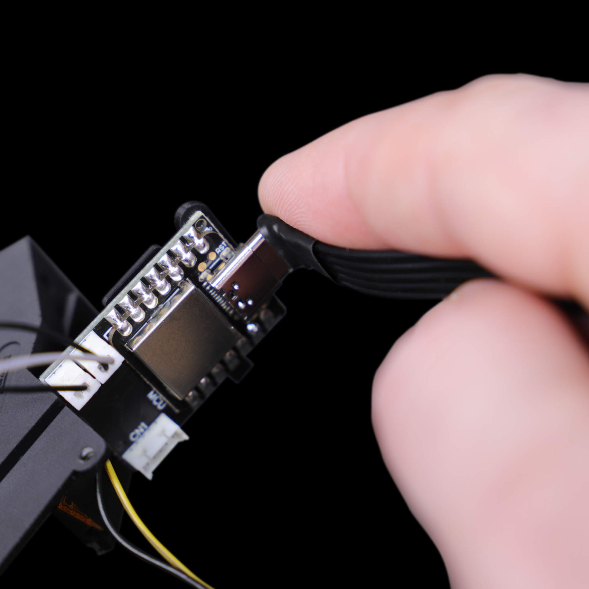
If you would like to power your entire KITT model via USB-C (recommended), remove any existing power sources, power mods, and/or batteries and continue to connect the angled end of the supplied USB-C cable to the USB-C port on the side of the screen controller.
Bonus feature
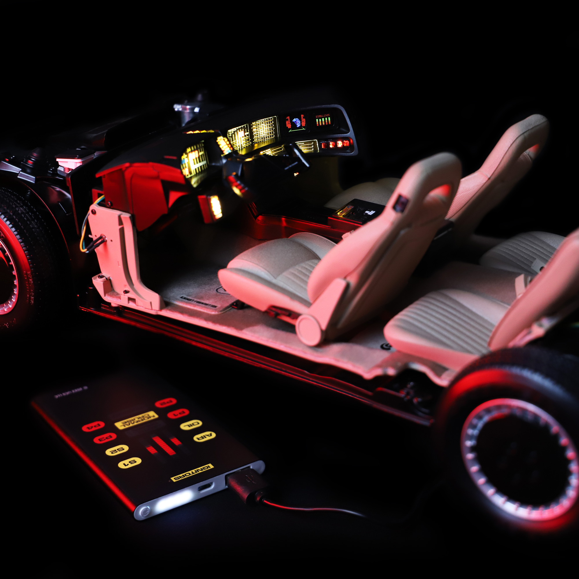
Did you know, that powering that model via USB-C will also allow you to use a rechargeable USB-C power bank for portability!
Also, having the USB-C cable installed will allow you to easily upload future software releases, patches and firmware upgrades to the monitors screen controller!
Power option 2 – Standard AAA batteries or third-party power mods
If you would like to continue using an existing power source, such as the standard AAA batteries or a third-party power mod, skip this step and do not install the provided USB-C cable. Instructions for providing alternative power to the monitor screens are provided later on in this guide.
Step 8 Fitting the monitor assembly to the dashboard
Carefully insert the monitor assembly into the dashboard, checking alignment with the screw holes and that any cables don’t get trapped beneath the assembly.
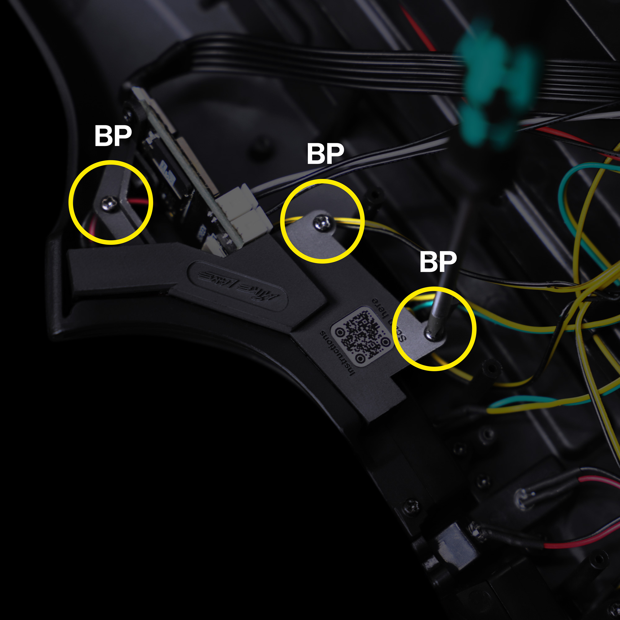
Using a PH0 screwdriver, install the monitor assembly using 3 x BP screws provided with Issue 4. You should have plenty of spare BP screws by the time you reach this stage.
Step 9 LED (G) adjustment
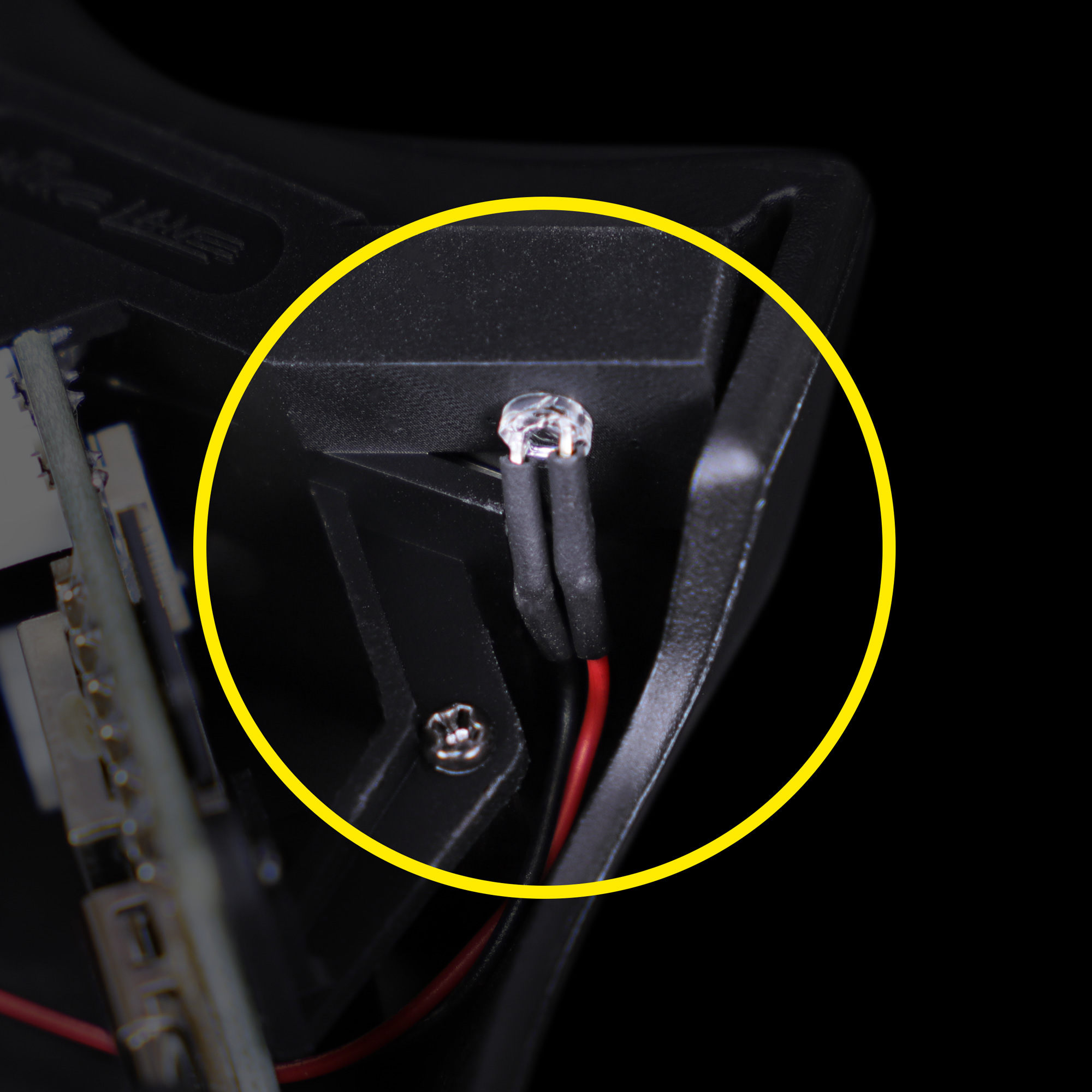
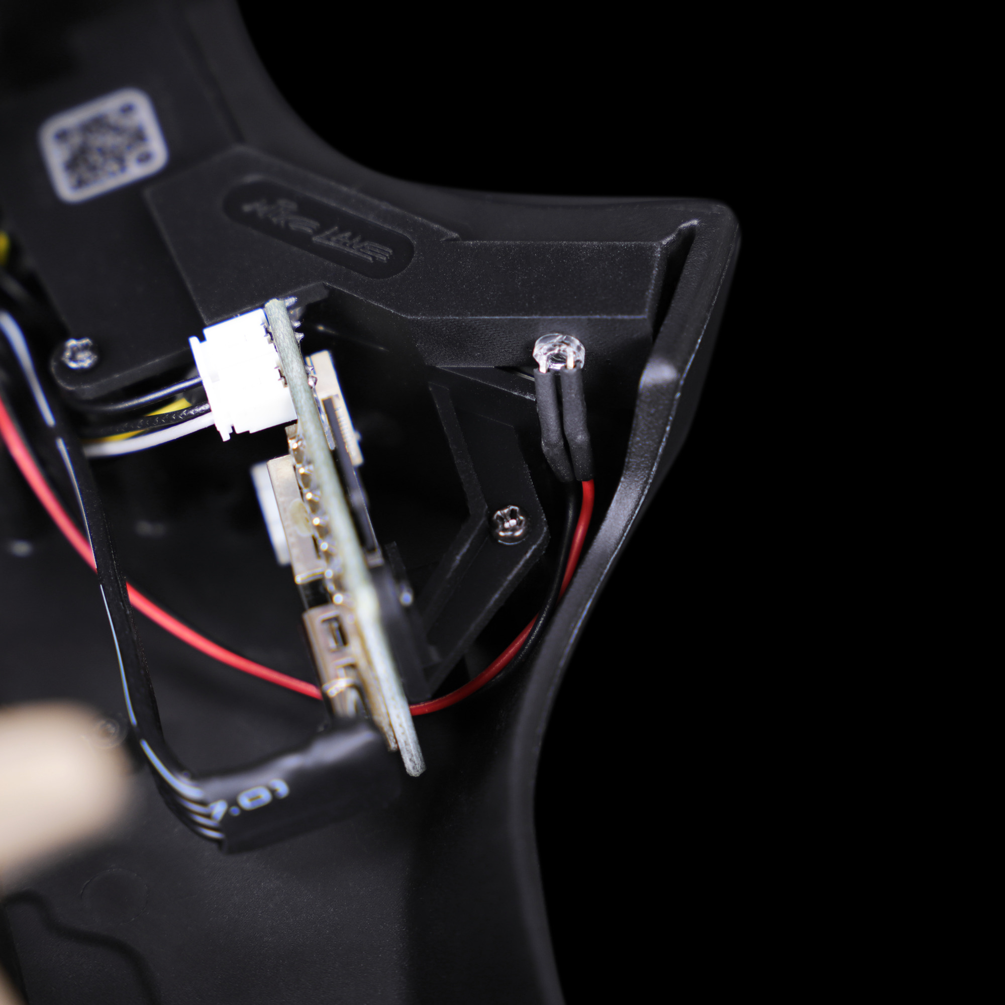
After installing the monitor assembly, carefully bend LED part 44B (G) with the red cable downwards into the dashboard.
Tuck the red and black LED cable beneath the monitor bracket and circuit board. This will help hide the cable from view once the installation is complete.
Step 10 Fitting the remaining stock dashboard parts
Epic mod incoming
At this stage, it’s worth noting that there is a future, pretty epic mod incoming – the Electronic Dashboard, Scanner and Alpha Circuit Pro:
If you’re interested in this upgrade, it would be worth holding off installing the remaining stock parts of the dashboard to allow easier access in future. In the meantime, if you would like to enjoy the monitor animations you can skip to Step 14 and continue to connect the electronics.
To be the first to know when this new upgrade is available, please subscribe to my mailing list here.
If you’re happy to continue with the stock dashboard parts, continue with the magazine instructions at Issue 48 – completing the underside of the dashboard and steering wheel assembly.
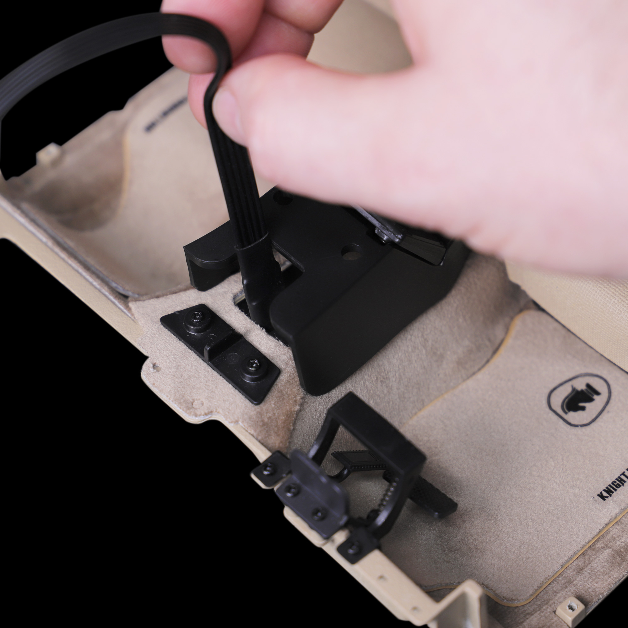
Route the LED, USB-C (if installed at step 7) and monitor cables under the cutout section of part 48A. When fixing part 48A ensure no cables are trapped beneath.
Remember that part 48H is not needed and will not be fitted as part of this upgrade.
Step 11 Running the cables back to the main circuit board
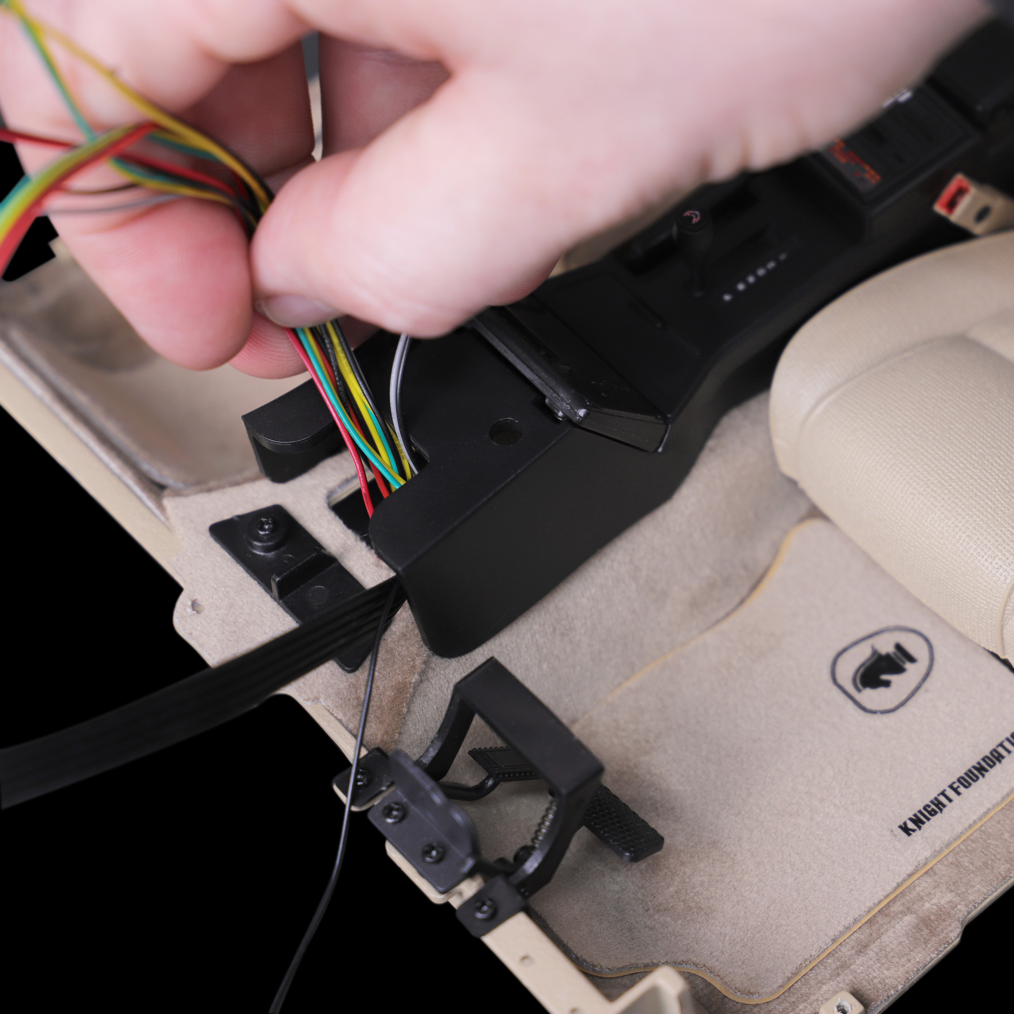
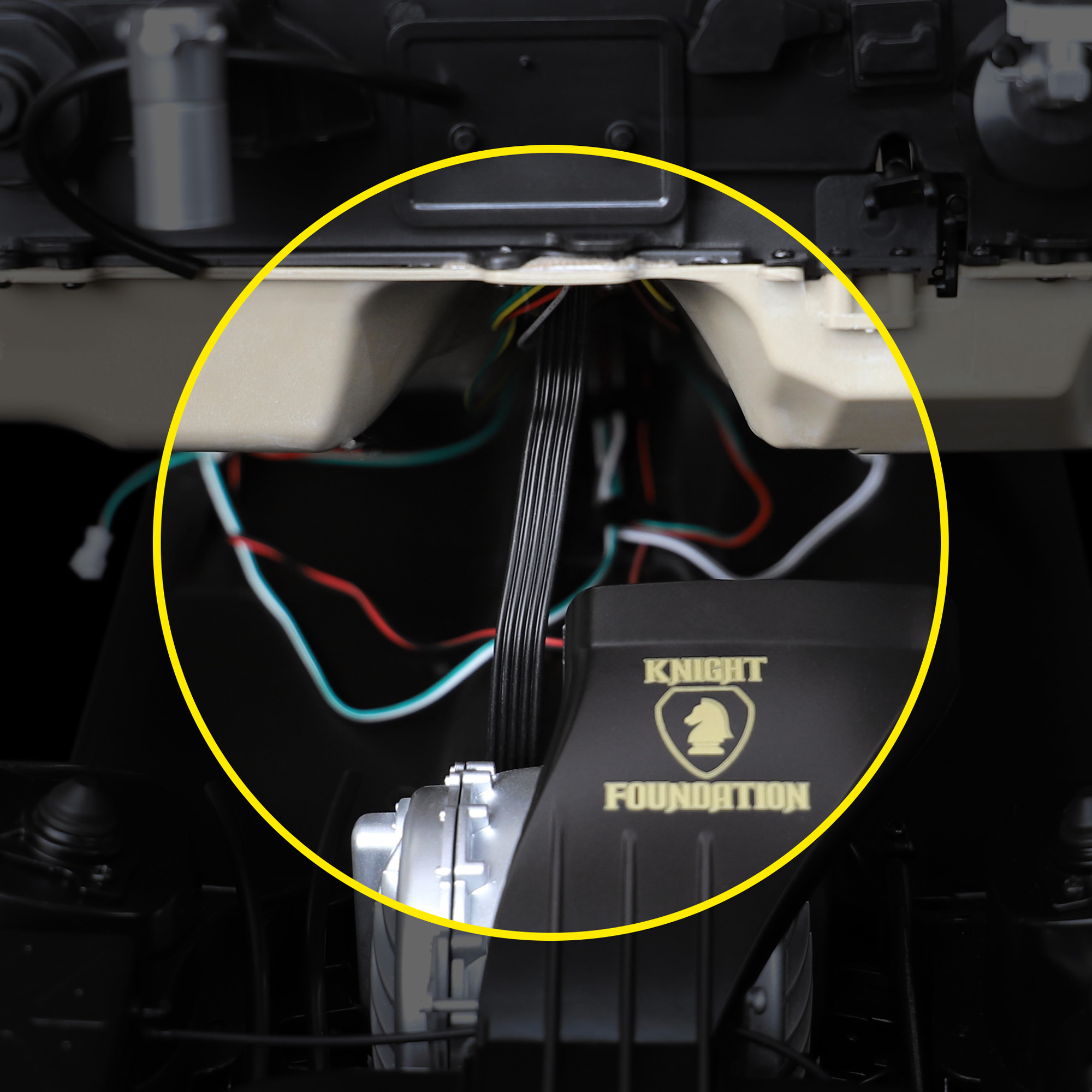
As per the magazine’s instructions at Issue 65, feed all the dashboard cables and USB-C cable (if installed at step 7) through the centre console and footwells (part 52A).
Step 12 Routing the USB-C cable through the engine bay
All of the dashboard cables, except for the USB-C cable, will route back towards the rear of the model to the main circuit board.
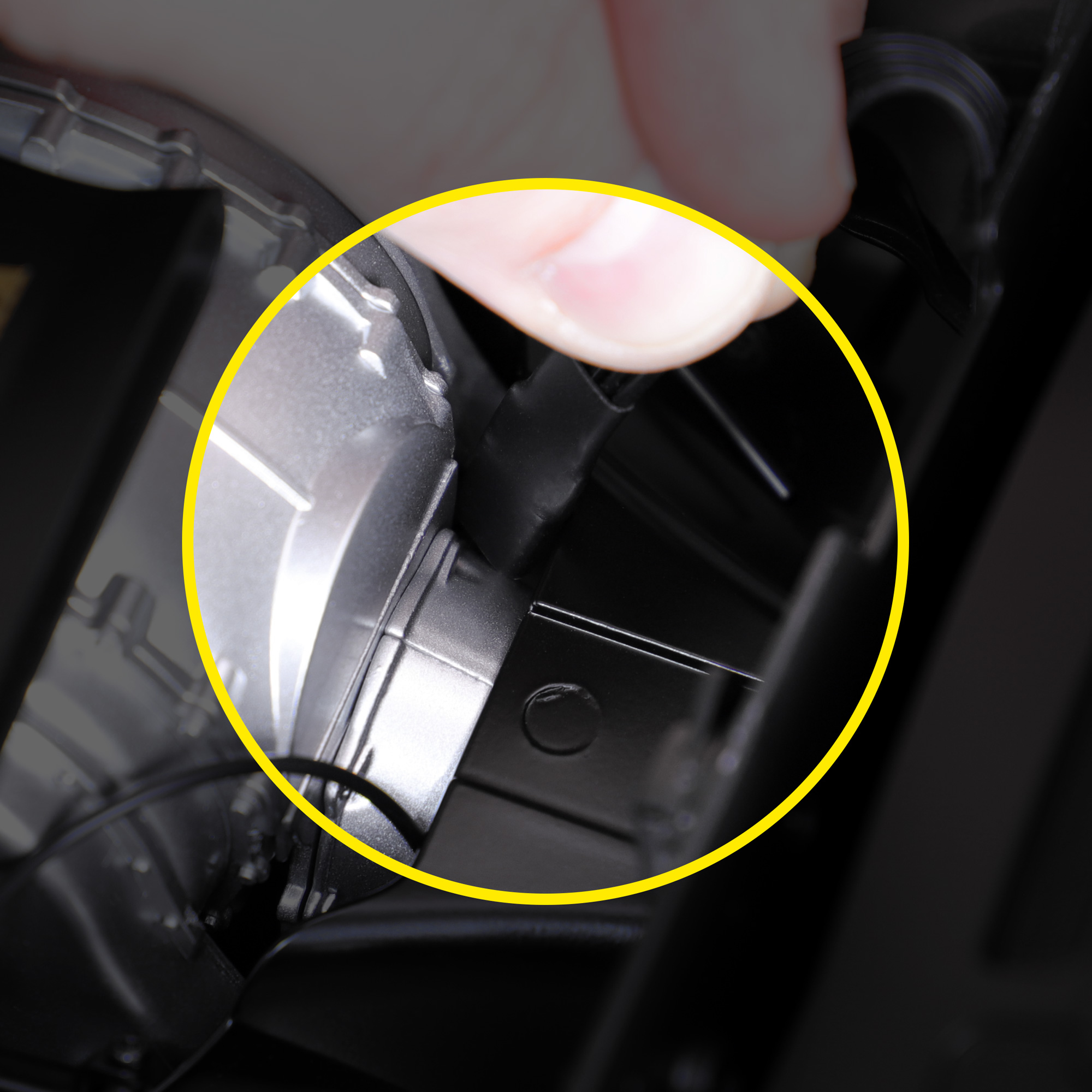
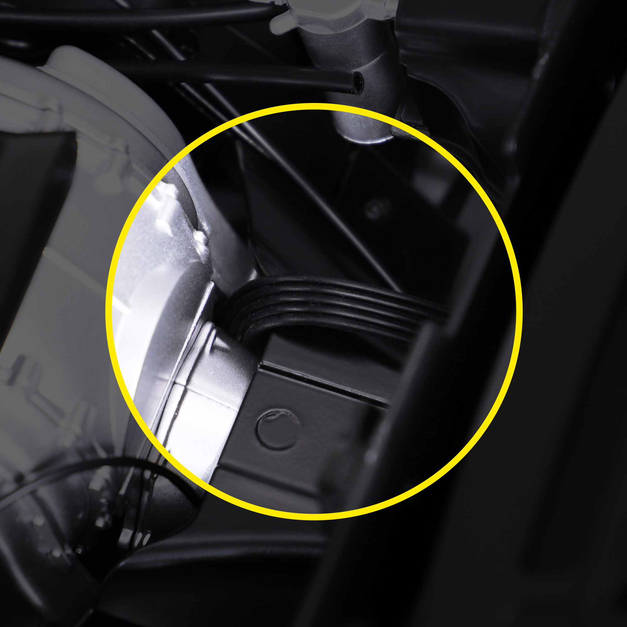
If you’ve chosen to power you model via USB, route the USB-C cable forward beneath the footwells and down the right-hand side of the turbine engine so that it appears beneath the model.
Step 13 Routing the USB-C cable beneath KITT
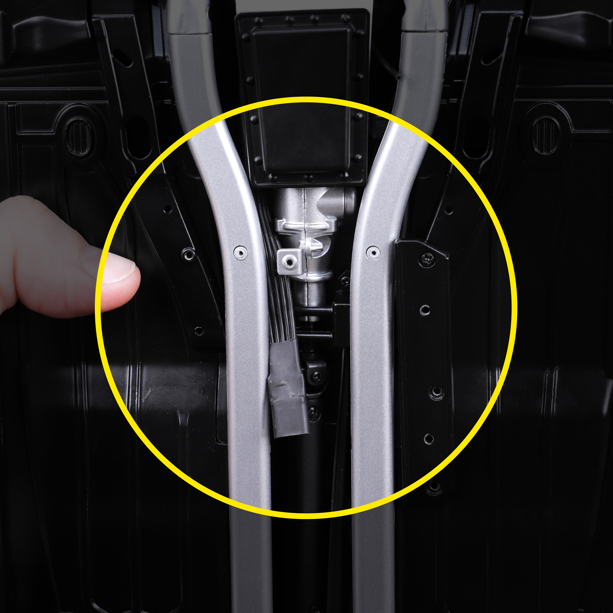
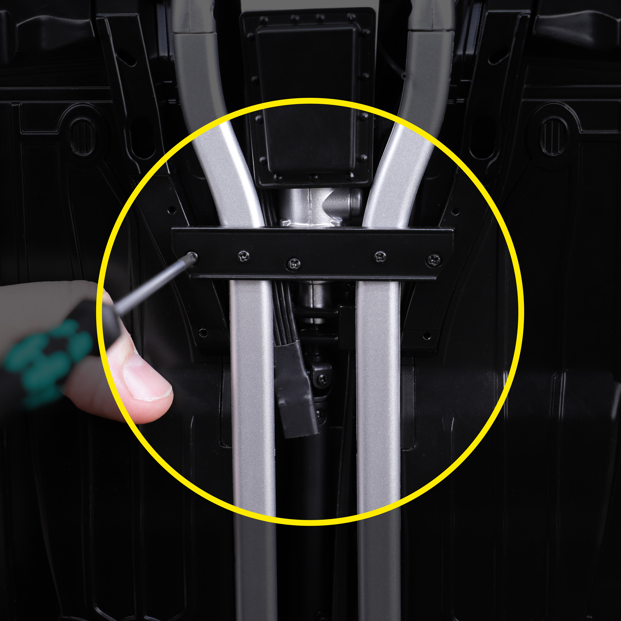
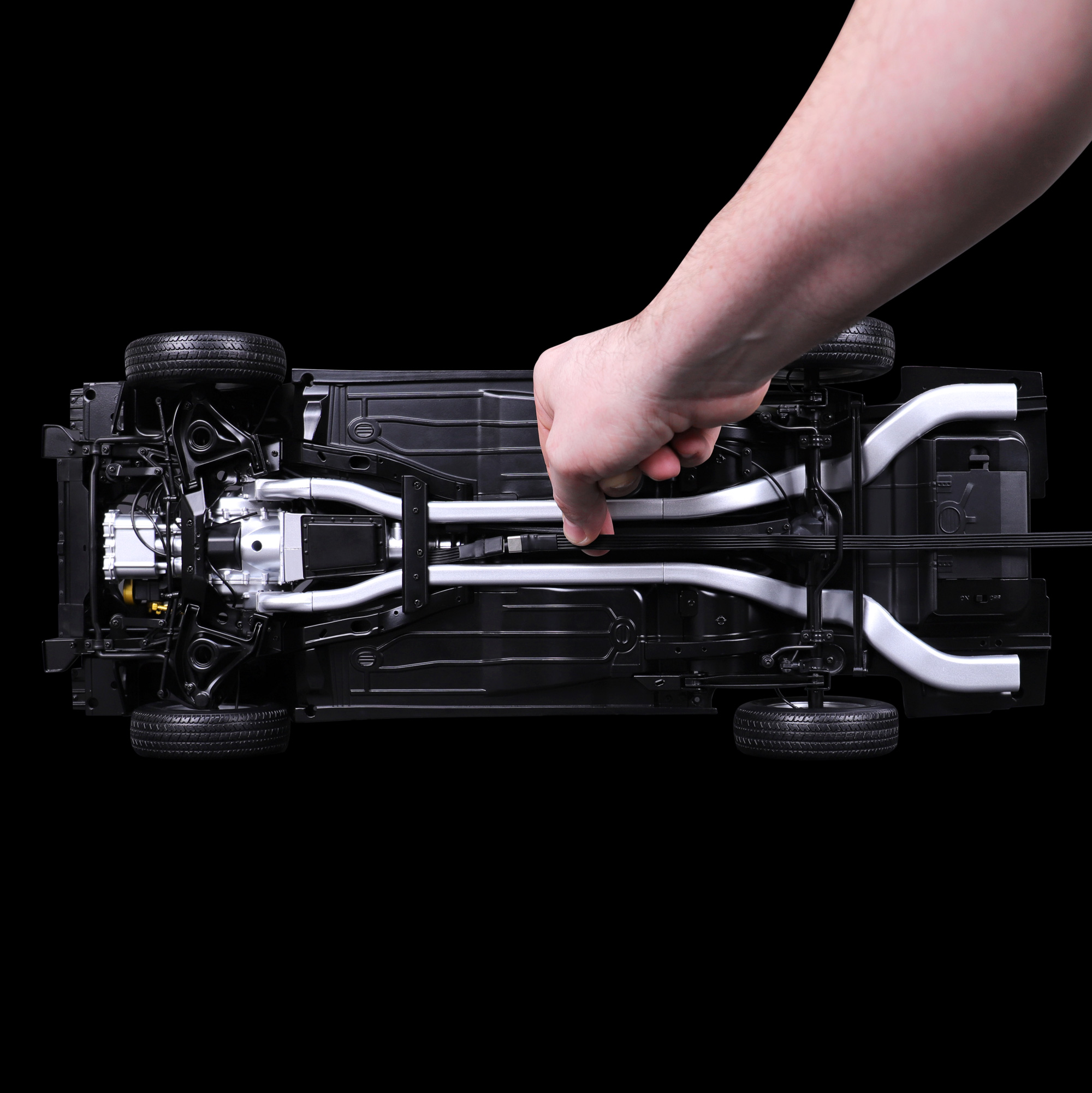
Temporarily remove the bracket beneath KITT holding the silver exhausts in place, lift the left exhaust slightly and pull the USB-C cable through.
Reattach the exhaust bracket to keep the USB-C cable in place.
Step 14 Cable connections to the main circuit board
Disconnect the stock LED cable from socket H (part 44C). These LED’s are no longer needed and will be replaced with the dashboard monitors.
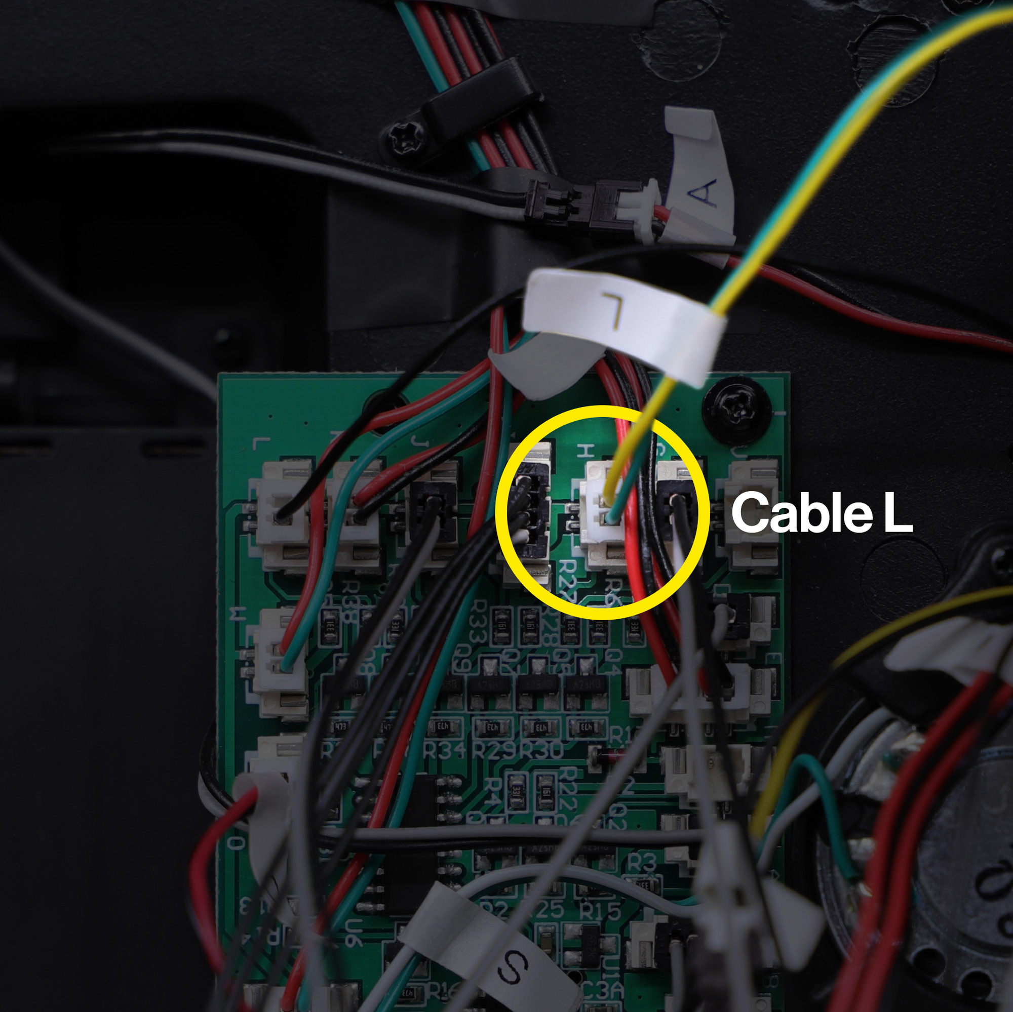
Disconnect cable L (part 44E installed at Issue 44) from the main circuit board and move it to socket H.
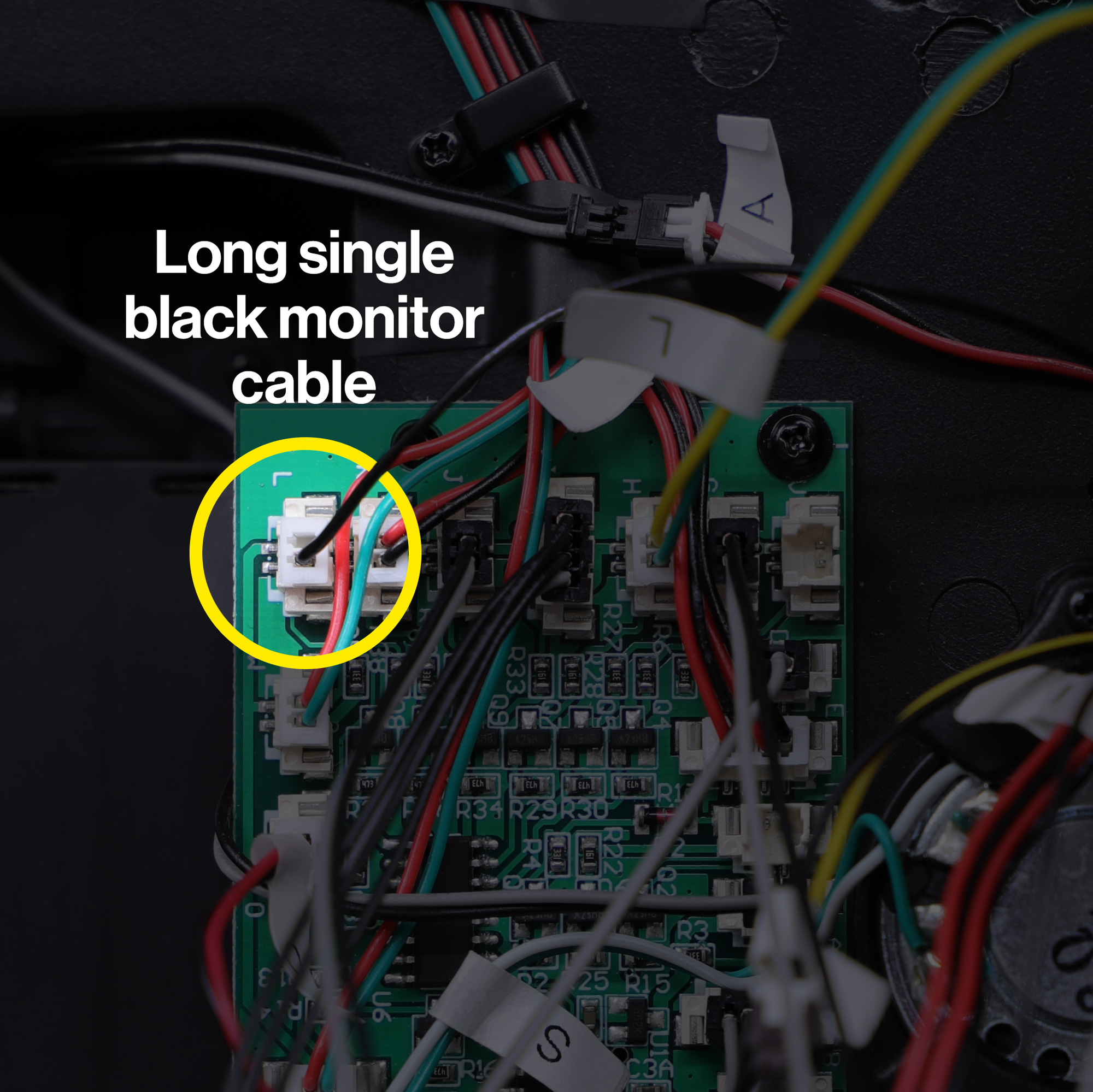
Connect the long single black cable coming from the dashboard monitors into socket L.
Switching the cables as detailed above may sound unusual, but this is an important step for the dashboard monitors to perform correctly.
Ensure that the cable colours and wire orientations match the photos exactly!
Step 15a Cable connections for USB-C power
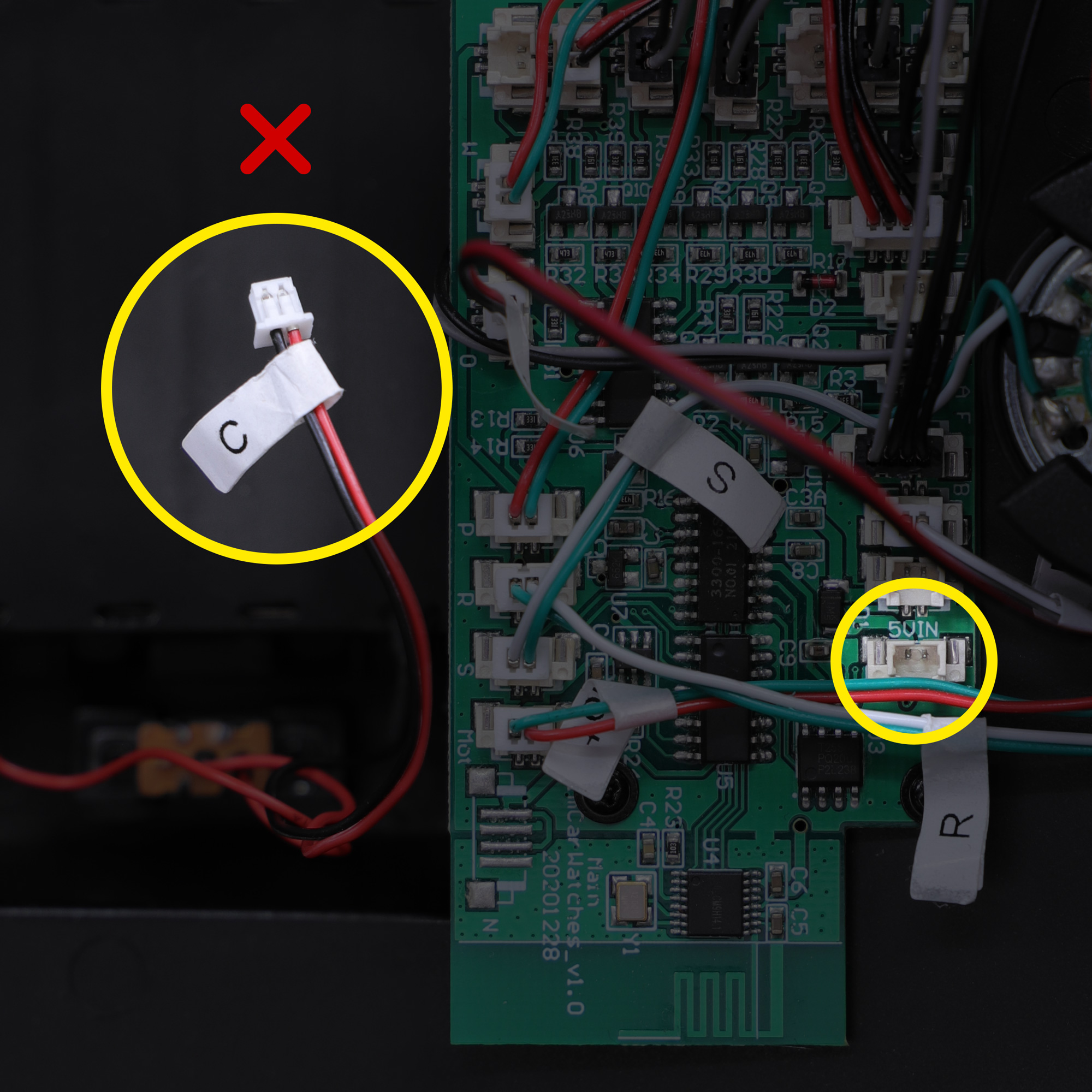
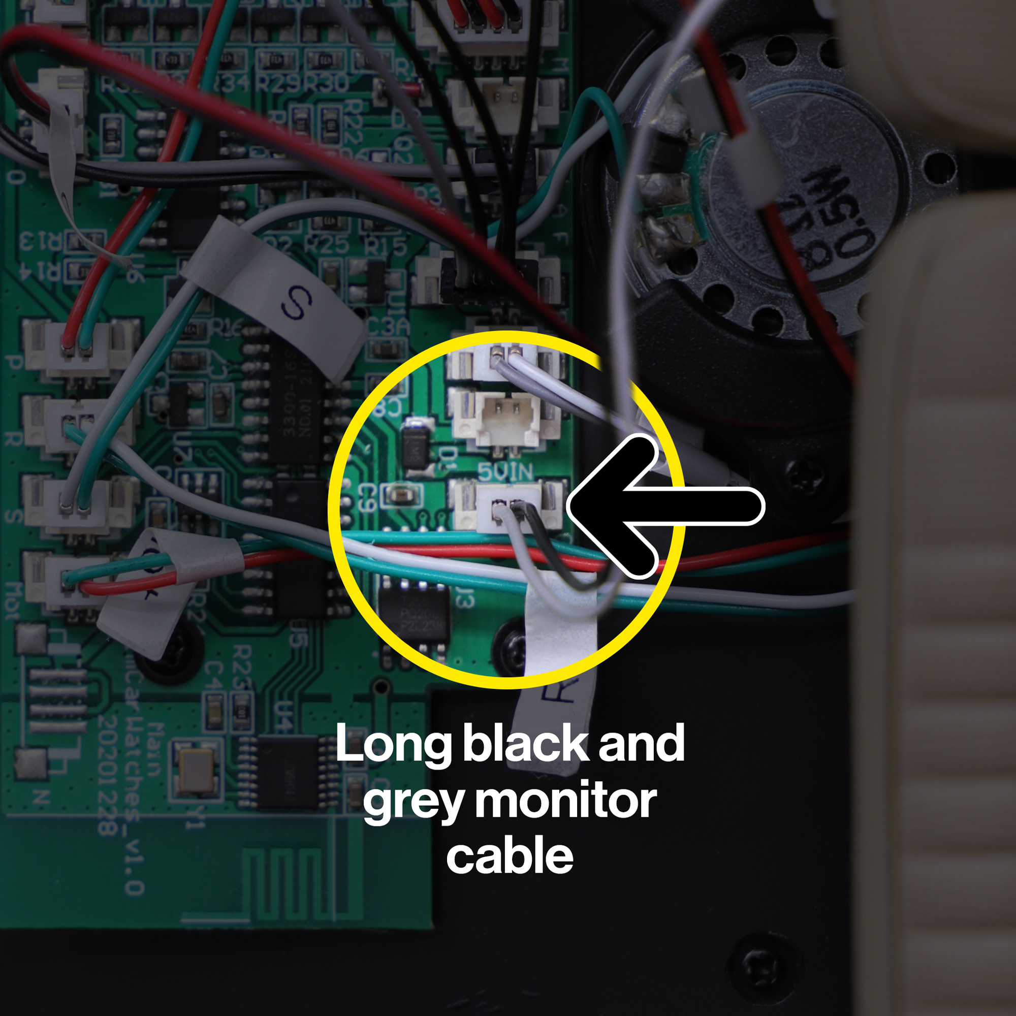
To power your model via the USB-C cable, disconnect the battery connector cable (C), or any other alternative power source from the 5VIN socket and replace with the long black and grey cable coming from the monitors.
Ensure that the cable colours and wire orientations match the photos exactly!
Step 15b Cable connections for alternative power sources
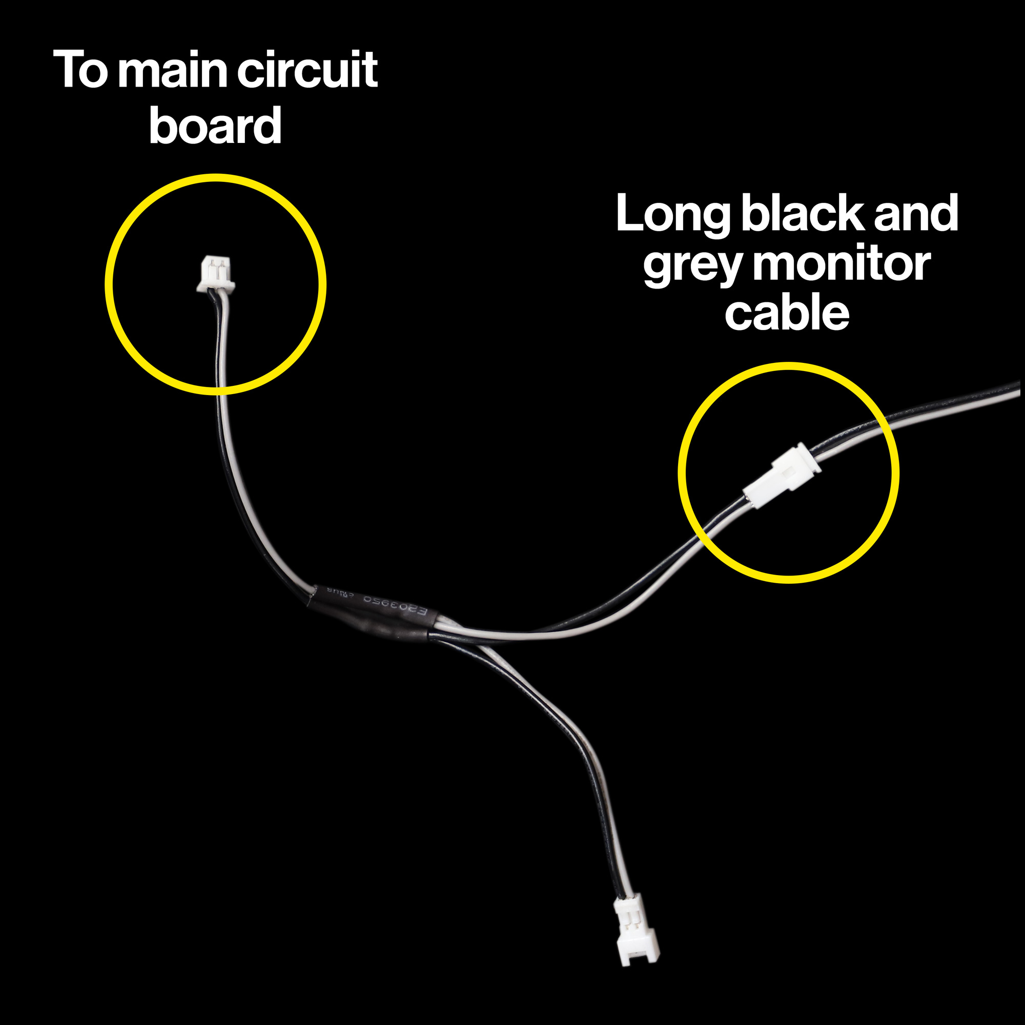
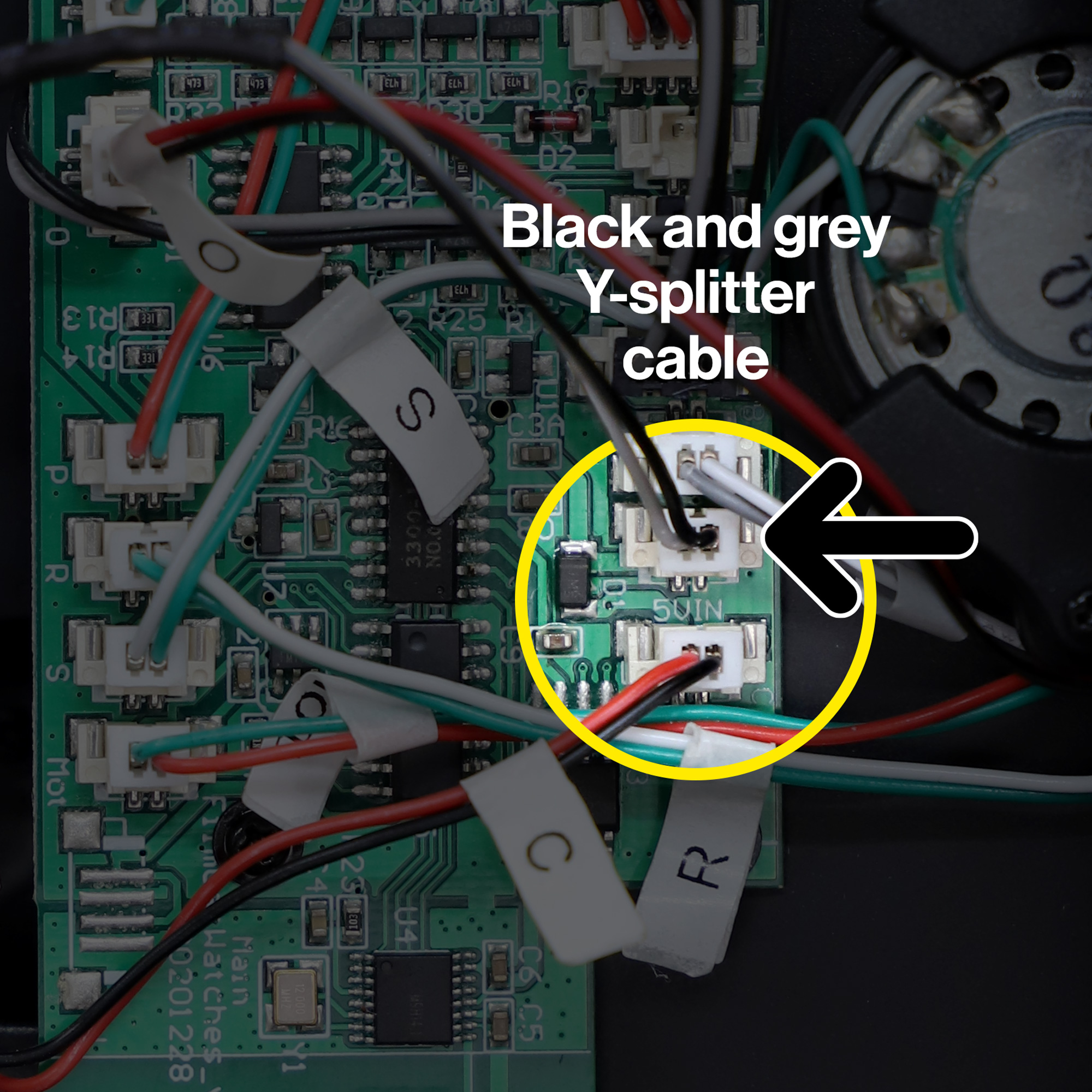
Alternatively, if you would like to continue using an existing power source, such as the standard AAA batteries or a third-party power mod, connect the black and grey Y-splitter cable into the spare socket directly next to the 5VIN socket and leave your existing power source connected to the 5VIN socket.
Then, connect the long black and grey cable coming from the monitors into one of the connectors on the Y-splitter cable.
The spare connector on the Y-splitter cable is provided for future modifications. Important: Do not connect anything else to this unless instructed to do so in future modifications.
Ensure that the cable colours and wire orientations match the photos exactly!
Step 16 Powering up
The installation is now complete!
If powering via the original AAA batteries or an alternative power source, you can now switch on power to the model.
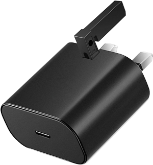
If powering via USB-C, you can now connect your power adaptor or power bank to the USB-C port beneath the model.
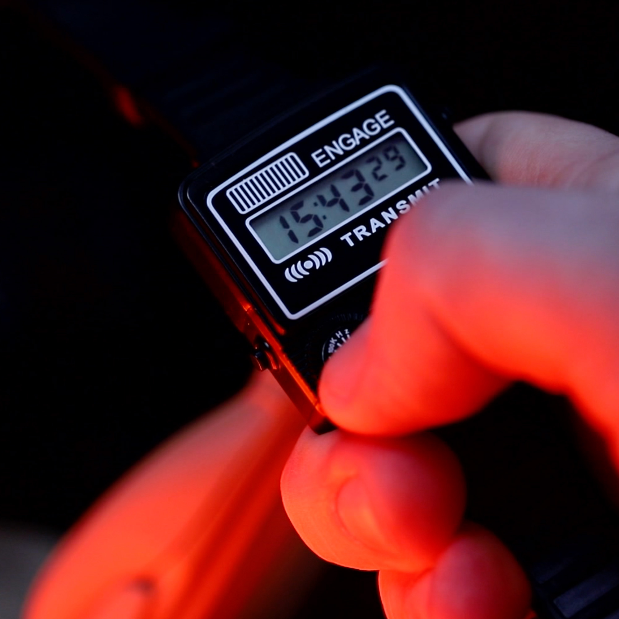
You’re now ready to activate KITT via the watch to enjoy your upgraded monitor screens.
If your monitor screens don’t behave as expected, please return to the instructions above and/or refer to the troubleshooting tips below.


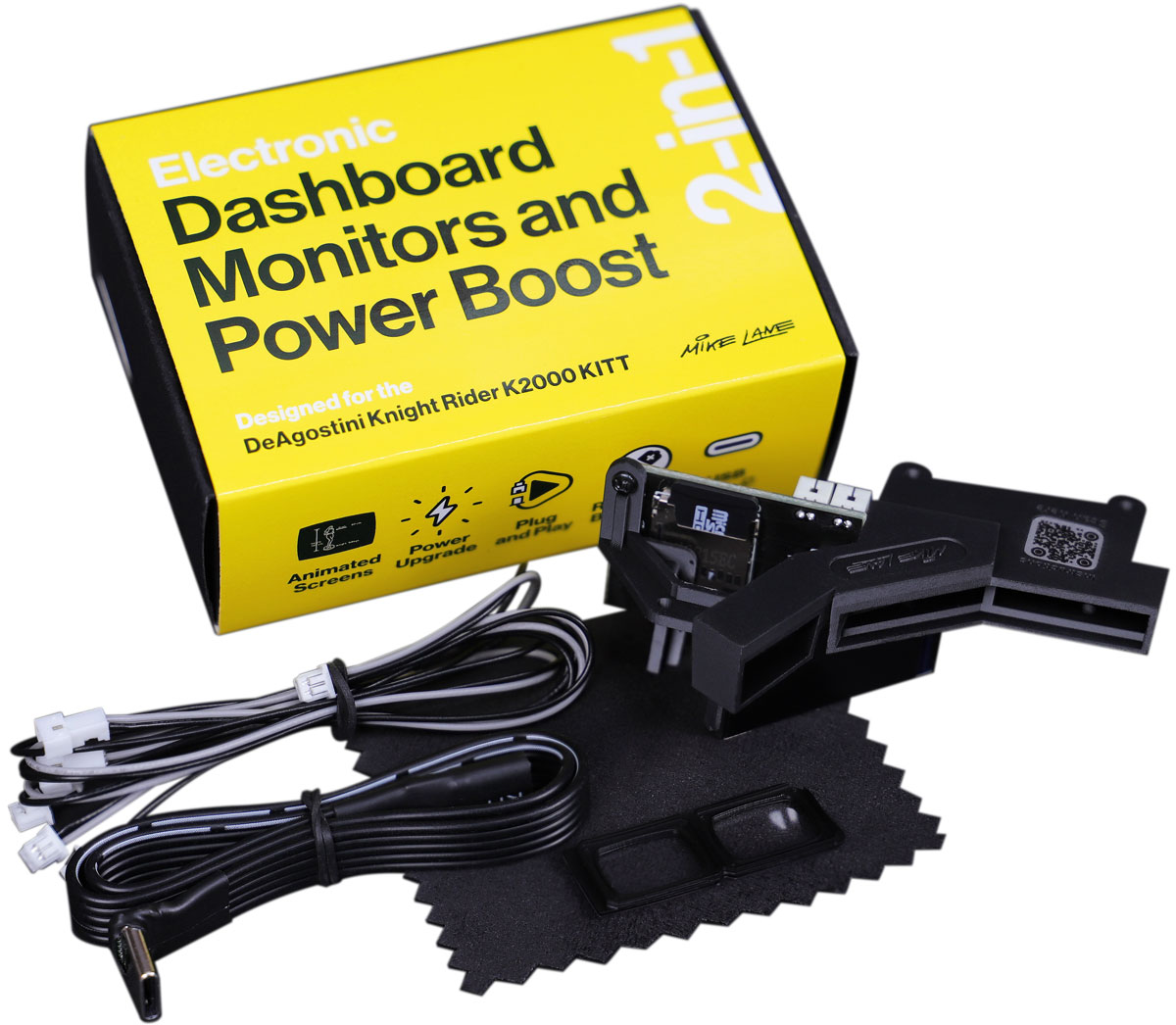
 This modification contains sensitive electronics. To avoid static shock which could damage the device, please ensure you handle the device with care and avoid touching the metal parts whenever possible.