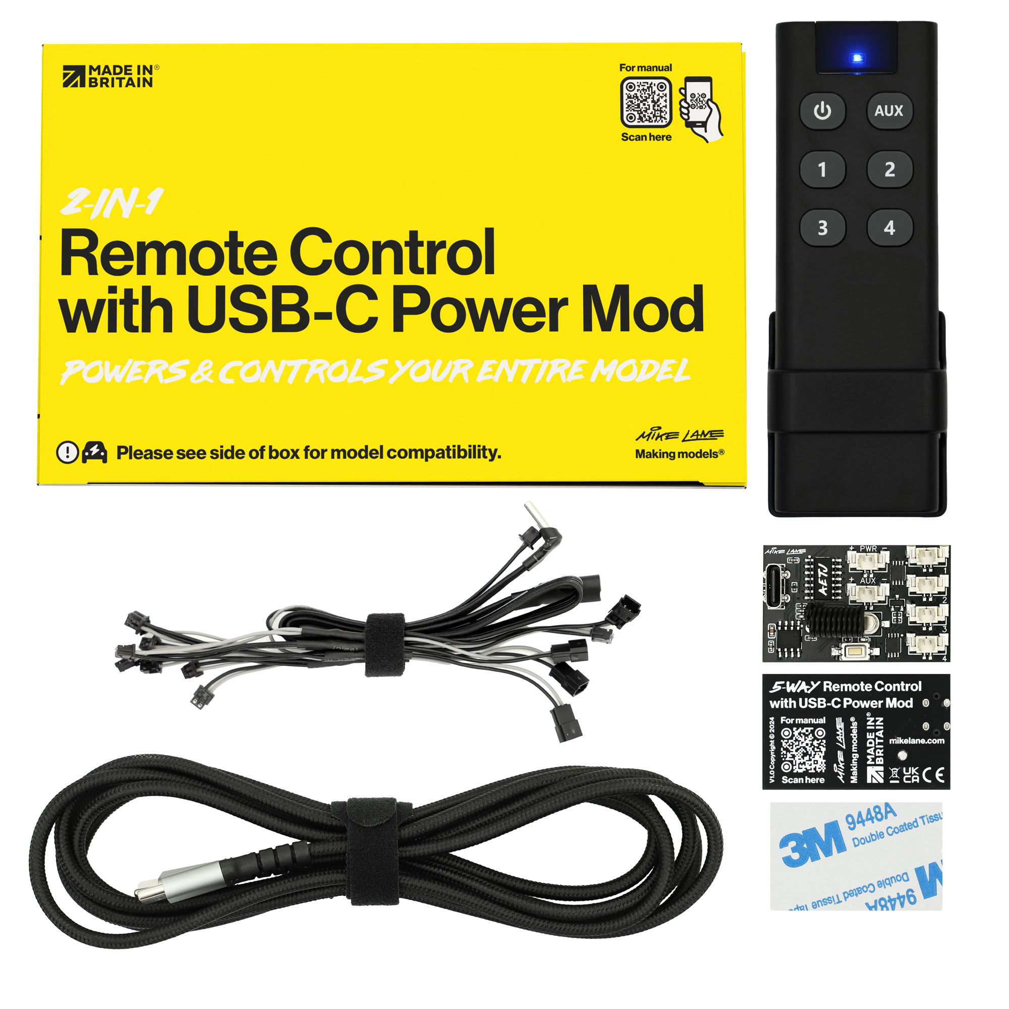
Designed for Issue 93 of the Build the 1961 Jaguar E-Type by Agora Models.
The simple rule
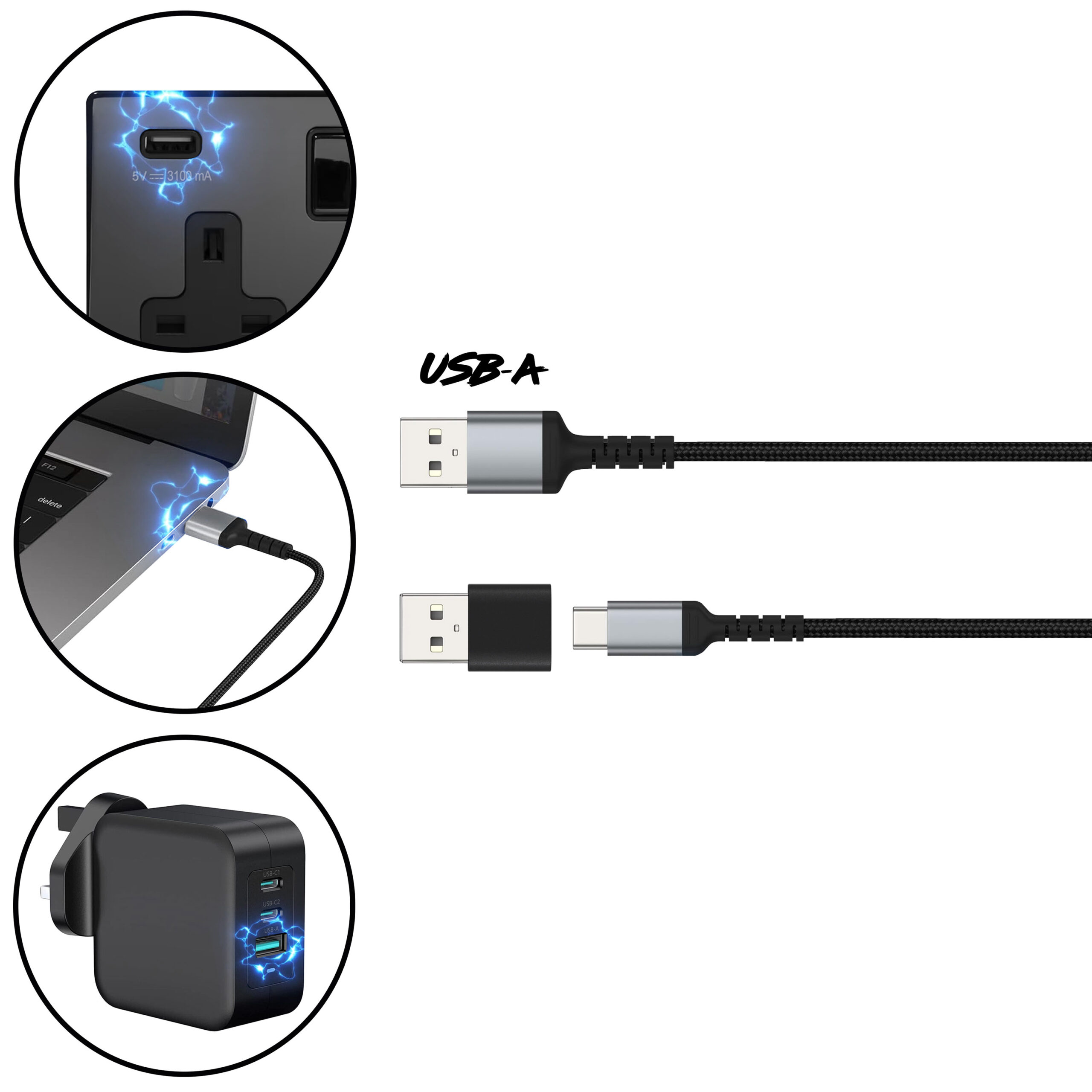
Stick to USB-A for safe, stable 5V power.
Only use direct USB-C if you know the adaptor outputs a fixed 5V.
You can power your model using any standard USB-A power sources, including:
In-wall USB sockets rated at 5V (e.g. 5V 3.1A/3100mA is ideal)
USB ports on laptops, PCs or Macs (most supply a fixed 5V)
USB power banks with a fixed 5V output
Powered USB hubs that provide a fixed 5V output
Or a dedicated USB power adaptor:
Mains power adaptors with USB-A port that provide a fixed 5V output
If your kit includes only a USB-C cable, you’ll need either:
- a dedicated 5V 2A USB-C power adaptor, or
- a USB-C to USB-A adaptor to connect to standard USB-A sockets (such as those found in wall outlets, PCs, or USB power adaptors).
Never attempt to power the model via any other method, including:
Third-party power mods or alternative power sources.
Multiple power mods at once
This product is a complete power mod solution. Connecting more than one power mod together is dangerous and may cause serious damage or fire risk. If another mod is already installed, remove and fully disconnect it before starting.
The existing battery box or batteries.
This power mod replaces the battery system entirely. Connecting both may cause malfunction or damage..
Fast chargers, smart chargers, or variable-voltage adaptors when using USB-C
If connecting directly using USB-C, avoid using adaptors with technologies such as USB Power Delivery (PD), Quick Charge or Fast Charge, which can output higher voltages (e.g. 9V, 12V, 20V). If proper voltage negotiation doesn’t occur, the adaptor could deliver too much power and damage the circuit. Using USB-A sockets however is usually safe and they almost always output a fixed 5V, which makes them much safer for your power mods.
Technical information
This product requires a stable 5V (max) 2A (min) power supply to function reliably.
To clarify:
- 5V is the maximum voltage — anything higher may damage the product.
- 2A is the minimum current — higher current (e.g. 3.1A/3100mA) is perfectly fine. The device will only draw what it needs.
So, for example, a wall socket with USB-A connection rated 5V 3.1A is ideal and completely safe to use.
- Connect the USB‑C cable to the Mike Lane Remote Control circuit board and plug it into a power source (e.g. power bank, laptop, or USB‑C adaptor).
- A blue LED will light up dimly on the circuit board, then turn off after around 10 seconds.
- Press the programming button once.
- The blue LED will begin flashing, indicating the board is ready to receive remote codes.
- On the remote, press the buttons 1, 2, 3 and 4 in order, waiting one second between each press.
- Then press the POWER and AUX buttons—in that order.
During the programming process, the LED on the circuit board will remain steadily lit and will blink each time a button is pressed, confirming that the button code has been received.
Once all buttons have been successfully coded, the blue LED will flash several times to indicate that programming is complete.
Bind the buttons in this sequence:
- Button 1
- Button 2
- Button 3
- Button 4
- POWER
- AUX
Syncing the Power Mod with the Stock Mainboard
Important: If you’re binding a remote after connecting power and linking to the stock mainboard, you must power cycle the Power Mod to ensure proper synchronisation.
To do this, disconnect power, wait 20 seconds, then reconnect. This allows the Power Mod to correctly sync with the stock mainboard.
You can start installing this mod from issue 93 when the stock PCB is supplied, however, you will need components from issues 96 to complete and test the installation.
If the model has been completed, the rear underfloor will need to be removed from the body to access the connections on the PCB.
This is fitted to the car in issue 97, refer to the instructions in this issue for details of how to remove it.
- Disconnect cables 2, 3, and 4 which lead to the stock circuit board, but leaving the short extension leads to each socket in place.
- There are two plug ends to the supplied Y-splitters, one with a smaller 1.25 JST plug and the other with a larger 1.5mm ZH plug. Connect the larger plug (1.5mm ZH) of each Y-splitter to the corresponding short stock extension lead coming from the original board.
- Then, bridge the original stock cable connections by connecting a Y-splitters between their connections. For instance socket 2 from the stock mainboard > Y-splitter > to stock cable 02.
- Connect the remaining smaller plug of the Y-splitter cables to one of the supplied extension cables and then connect these extensions to the Mike Lane Remote Control circuit board as follows:

| Stock Board | to | Mike Lane Remote Control Board |
| 2 | 1 | |
| 3 | 2 | |
| 4 | 3 |
- Unplug the battery box cable from the stock circuit board labelled 1. The battery box will no longer be required.
- Take the supplied red and black power cable and connect the end with the larger plug (1.5mm ZH) to the short extension lead coming from port 1 on the stock board.
- Connect the other end of this cable with the smaller plug to the socket on the Mike Lane Remote Control circuit board labelled ‘PWR’.

- Attach the Mike Lane Remote Control circuit board to the inside of the back of the dashboard housing using the supplied double-sided 3M pad.
- The cables that connect the stock PCB to the Mike Lane Remote Control circuit board will run neatly under the transmission tunnel between the seats.
- Connect the slimline USB-C extension cable to Mike Lane Remote Control circuit board. The angled head can orientate towards whichever side of the model you wish to exit from.
- Run the slimline USB-C extension cable out of the car via the nearest convenient hole in the chassis or engine bay. This will then discreetly hang from the bottom of the car.
- Ensure all your connections are made correctly, that the Remote Control has been coded to the Mike Lane Remote Control Power Mod and that all functions have been thoroughly tested before completing assembly of your model.
- For correct operation of the RF Remote Power Mod, the main power switch located in the Centre Console must be in the ‘OFF’ position.
- You can now connect the braided USB-C cable to this extension and connect to a power source.
- Test the operation of the board prior to replacing the floor and re-fitting the body.
The installation is now complete!
The buttons on the remote will now operate as follows:
| Button | Function |
| POWER | Switches lights and AUX sockets on / Turns all circuits off |
| AUX | Toggles Aux power circuit on / off |
| 1 | Lights |
| 2 | Brake Lights |
| 3 | Indicators |
| 4 | Action sequence |
If you make a mistake during programming or need to pair a new remote, simply restart the process. To do this, disconnect and reconnect the USB power to the Mike Lane Remote Control circuit board, then press the programming button again to re-enter pairing mode.
Recovery mode
Lost or damaged your remote? Don’t panic!
Our power mods include a built-in Recovery Mode, designed specifically for situations where the bind button is no longer accessible—such as after the build is complete.
With a special master recovery remote, you can bind a replacement remote without needing to press the bind button.
If you need a master recovery remote, please contact us—they’re available to purchase separately.
This upgrade features a special action sequence, programmed especially for this model.
This action sequence turns on the car, activates the brake lights and activates the turn signals before shutting everything off.
Power on demand
The AUX port on the Mike Lane Remote Control board delivers 5V at up to 1.5A, toggled with the AUX button on your remote.
That’s more than enough power for extra lights, motors, sound packs—or whatever ingenious upgrade you have in mind for your model.
Built for modders
Flexible: Drives your own custom electronics or third-party mods with ease.
Future-proof: Ready for any official Mike Lane accessories we may have in the pipeline.
Need something special?
If your project requires a connector or lead that isn’t in the box, just drop us a message—there’s a good chance we’ve already got the perfect solution waiting for you.
Polarity Warning
IMPORTANT: When connecting any third-party accessories or custom modifications to the AUX socket, ensure that the polarity is correct—positive to positive, negative to negative.
Incorrect polarity may cause permanent damage to the circuit boards and will void the warranty.
Use of third-party accessories or mods is entirely at the owner’s risk, as compatibility cannot be guaranteed. Always consult the manual and verify polarity before connecting any external device.
Please note
Every device is fully tested before dispatch to ensure a smooth, issue-free installation.
Most questions we receive can be resolved simply by carefully following the installation instructions step by step.
Facing issues?
If you experience any unexpected behaviour, please double-check the instructions and all cable connections carefully. If the issue persists, refer to the troubleshooting tips below.
Still need help? Don’t hesitate to get in touch—we’re here to assist you.
No power through the extension lead?
Pause! Don’t worry—the cables are fine. This is usually caused by certain smartphone mains adaptors or USB hubs that provide inconsistent voltage.
POSSIBLE CAUSES:
- Some mains adaptors—especially ones designed for smartphones—may seem to work when plugged directly into the power mod’s circuit board, but fail when used with the extension lead. This is a clear sign your power source isn’t suitable. There’s no fault with the extension lead or the mod—the power supply simply isn’t delivering a stable enough voltage.
SOLUTIONS:
- Check the ‘Power supply requirements’ section earlier in this guide.
- Switch to a dedicated, regulated 5V 2A USB power source.
- Avoid smartphone adaptors, hubs, or battery packs with variable voltage.
- Try using a USB-A connection with a USB-C to USB-A cable or adaptor.
Remote not behaving as expected?
If some buttons don’t work, or certain modes take multiple presses to activate, there could be a few simple causes.
POSSIBLE CAUSES:
- The remote batteries may be low
- Buttons are being pressed too quickly in succession
- You’re too far from the model
- The remote may need rebinding to the power mod
- Wireless interference or obstructions near the model
SOLUTIONS:
- Replace the batteries with fresh, non-rechargeable ones – rechargeable batteries often can’t supply sufficient voltage, even when fully charged.
- Use a Test Circuit Pro (if available) to check each battery
- Move closer to your model to ensure a stronger signal
- Ensure a clear line of sight between the remote and the model — avoid obstructions or interference near the antenna
- Press buttons slightly slower when switching modes — give the system time to respond
- Rebind your remote to the power mod using the instructions in the ‘Remote Control Functions’ section – you may have accidentally skipped some buttons during the original binding process
Remote was working… now it’s not?
If your remote suddenly stops working after previously pairing just fine, don’t panic—this is almost always due to an unstable or incompatible power adaptor. Even if everything seemed to work at first, these types of power sources can lead to intermittent connection problems over time.
POSSIBLE CAUSES:
- Some smartphone power adaptors or USB hubs use variable voltage, which can interfere with memory and connectivity.
- Battery banks can also cause issues if their power output isn’t stable.
SOLUTIONS:
- Check the ‘Power supply requirements’ section earlier in this guide.
- Switch to a dedicated, regulated 5V 2A USB power source.
- Avoid smartphone adaptors, hubs, or battery packs with variable voltage.
- Try using a USB-A connection with a USB-C to USB-A cable or adaptor.


