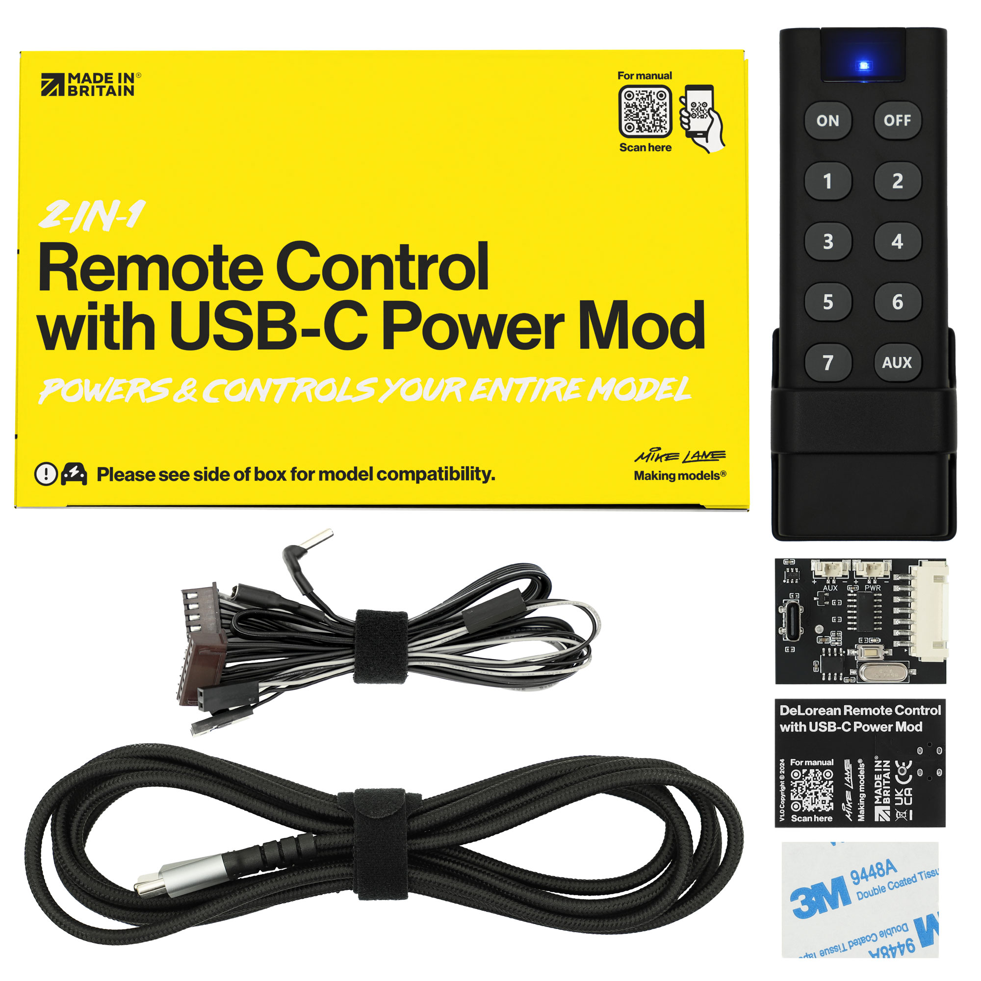
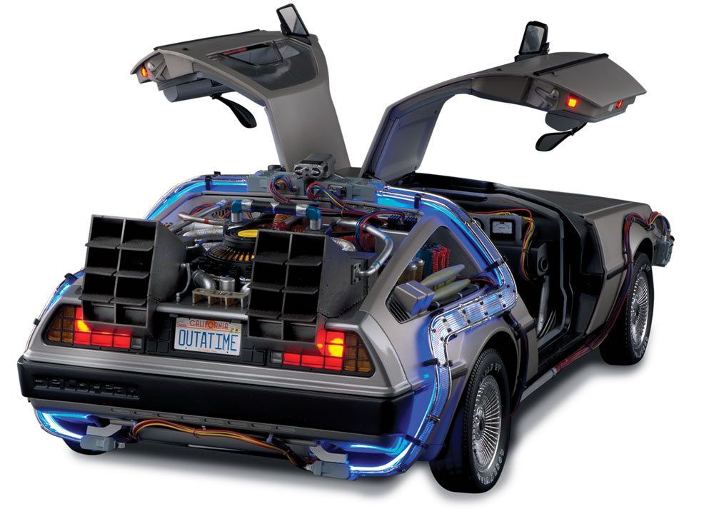
Designed for Issue 56 of the Build the DeLorean Time Machine by Fanhome/DeAgostini/Eaglemoss.
You can begin the installation of this mod from Issue 56 of the build.
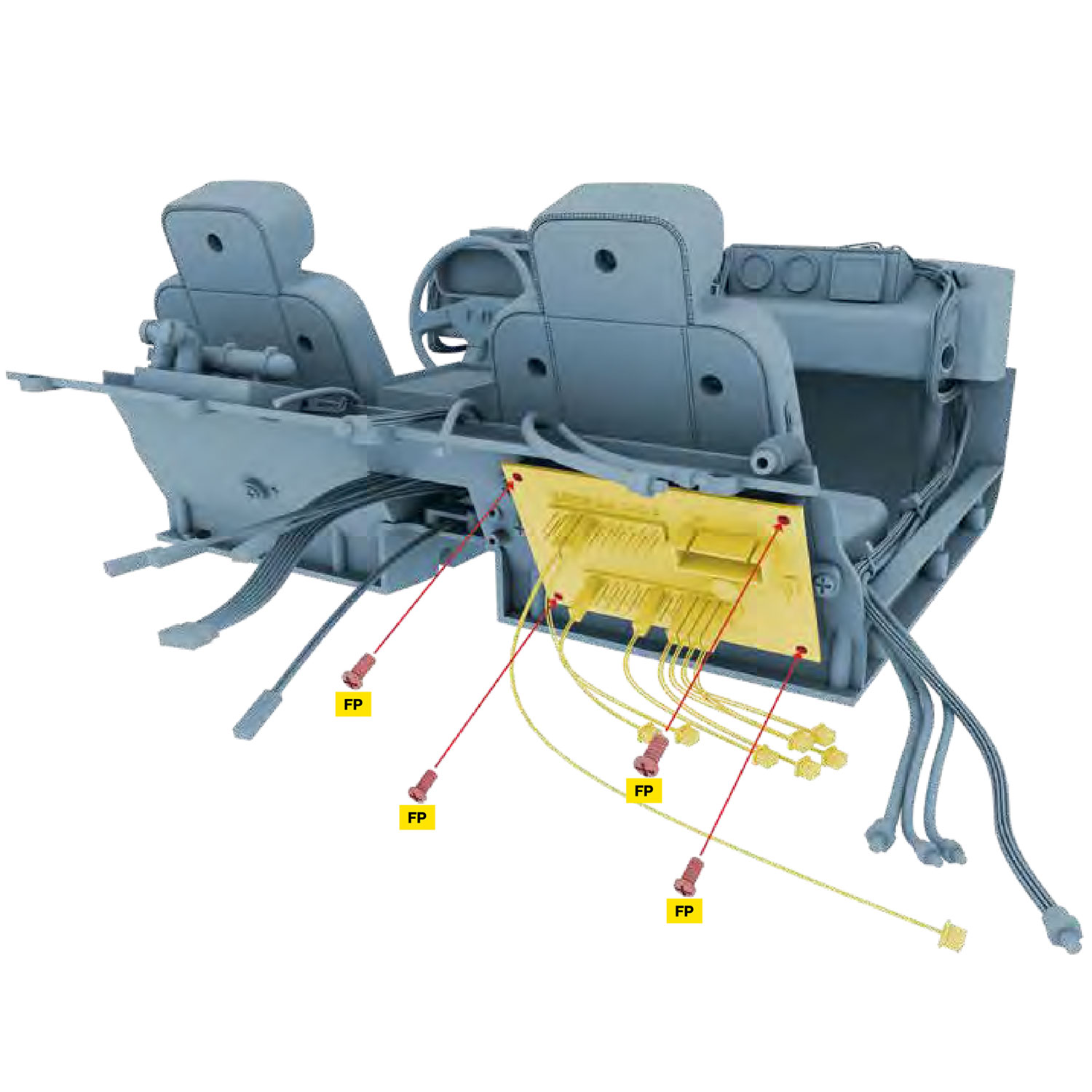
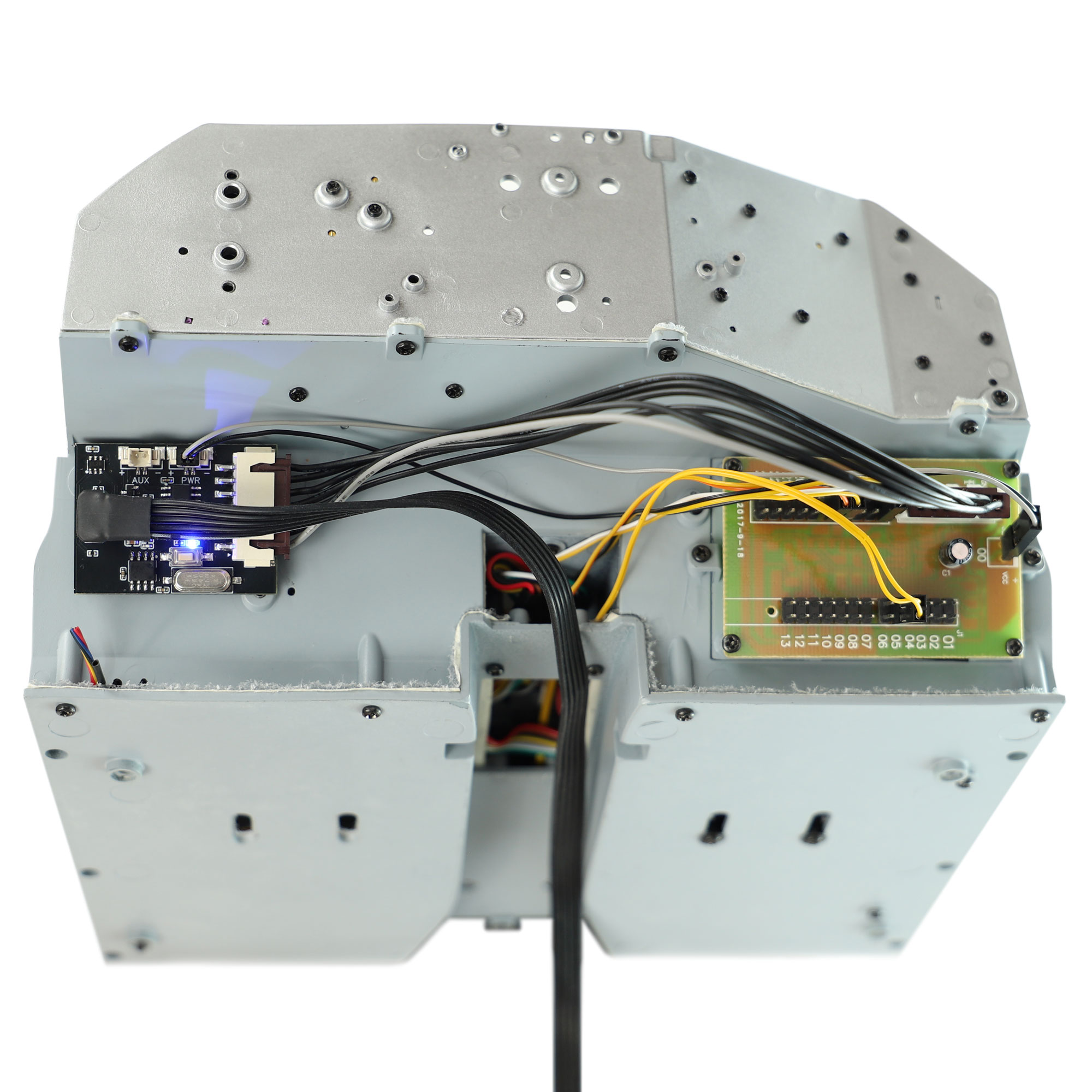
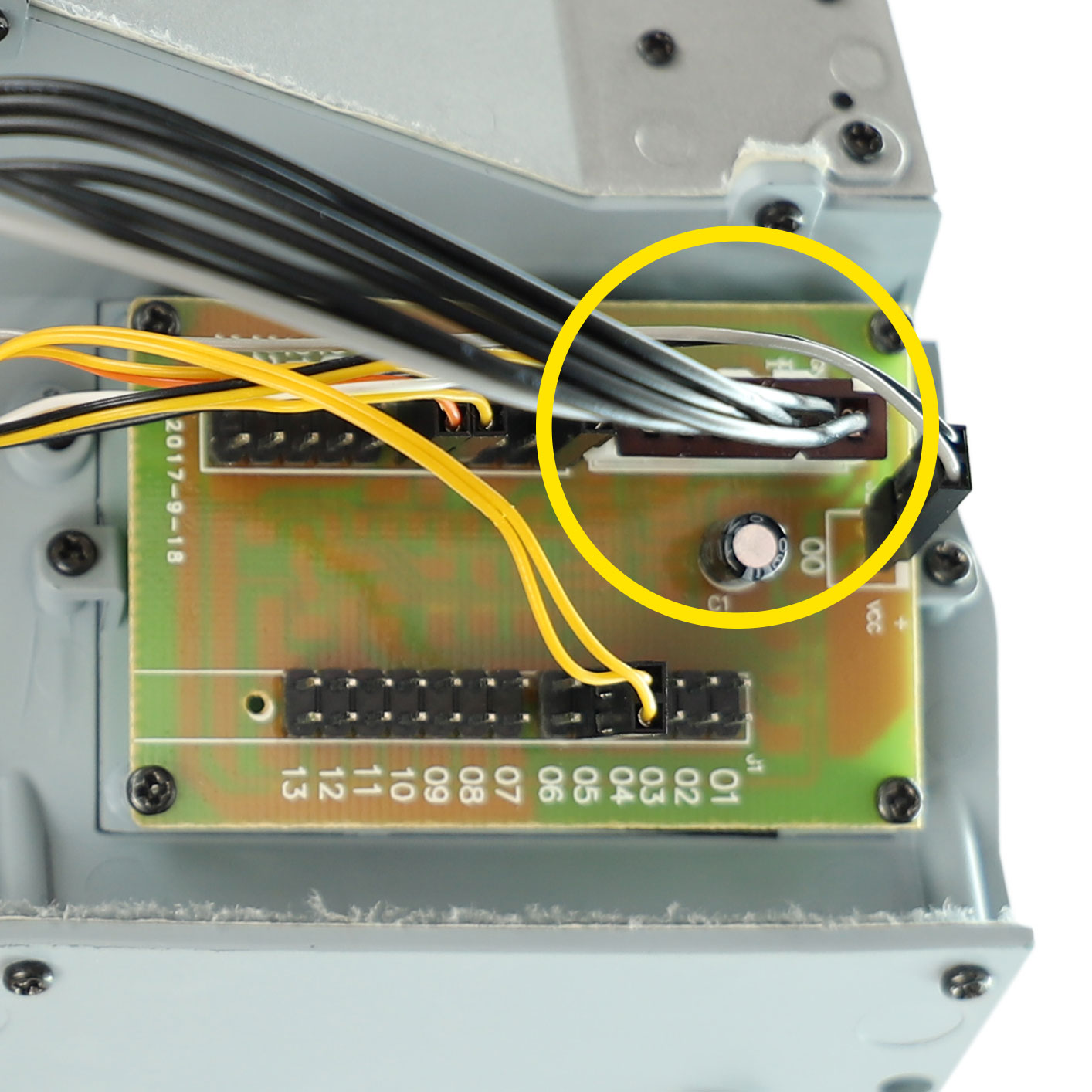
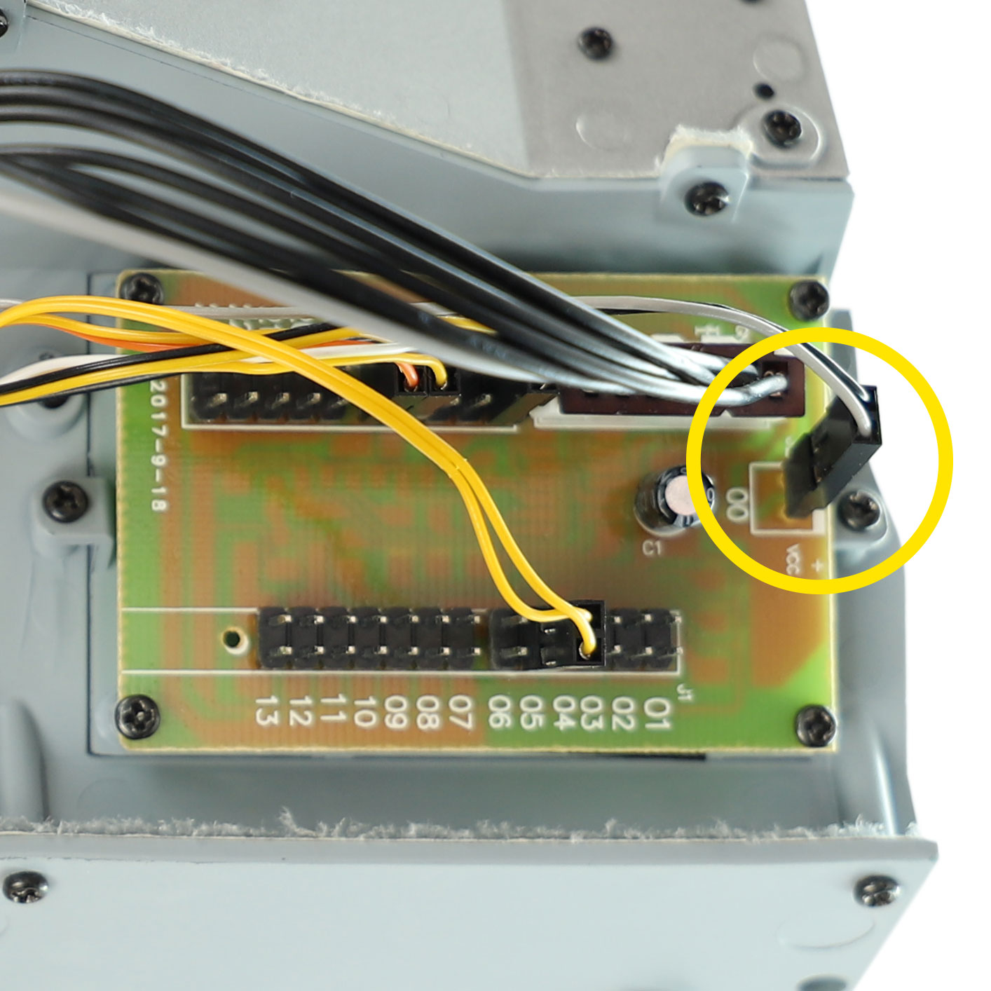
- Disconnect the battery box cable from the stock DeLorean mainboard (connected to the port labelled ‘00‘). The battery box will no longer be required.
- You will see 2 pins sticking out of the board where the plug was removed. Take note of the + and – symbols next to these pins as they are important.
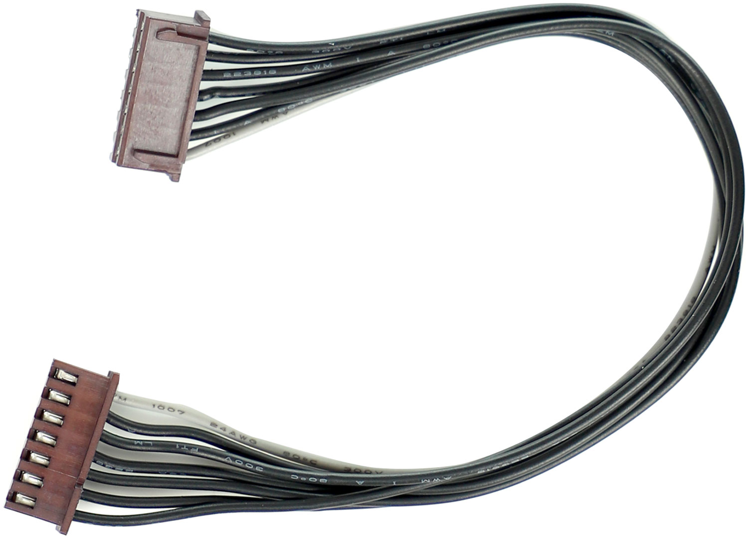
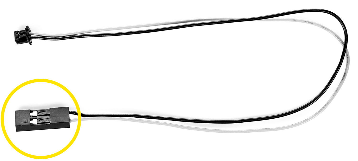
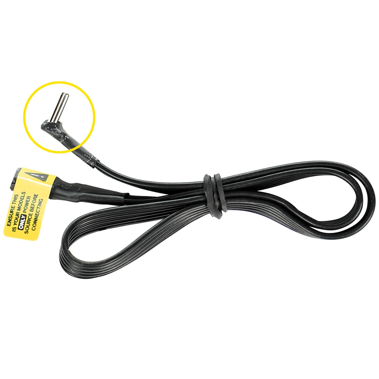
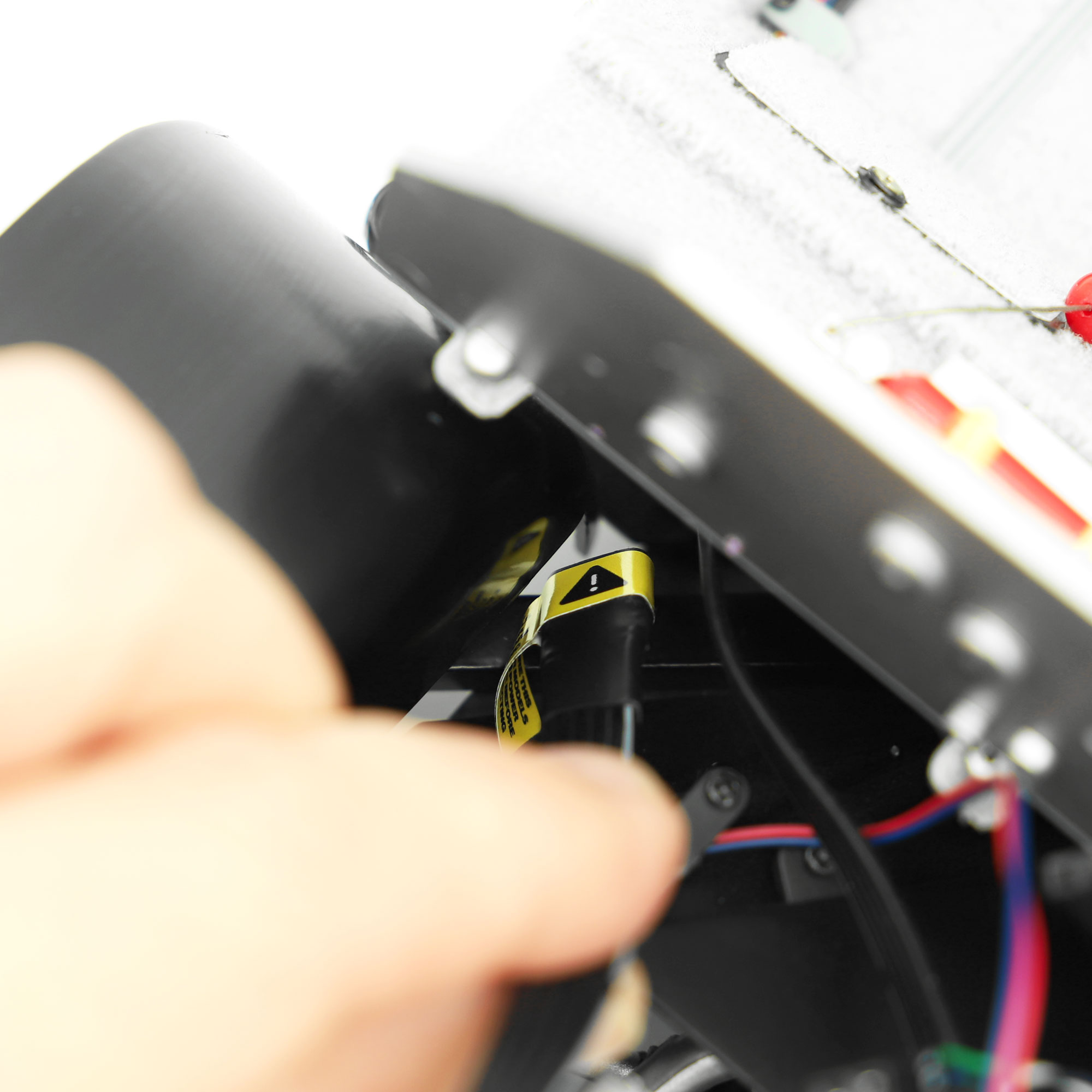
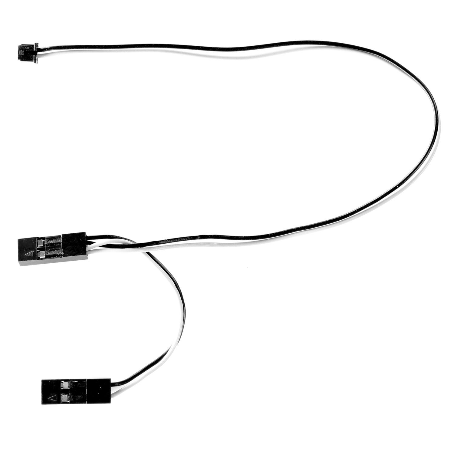
- Take the new power cable supplied within this kit as shown above and connect the large end to the pins on the stock DeLorean mainboard (where the battery box would normally connect). Check that the + pin is connected to the grey cable and the – pin connects to the black cable.
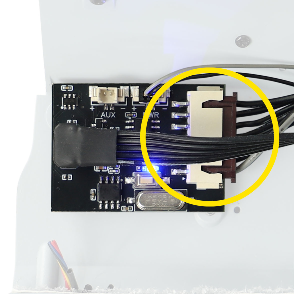
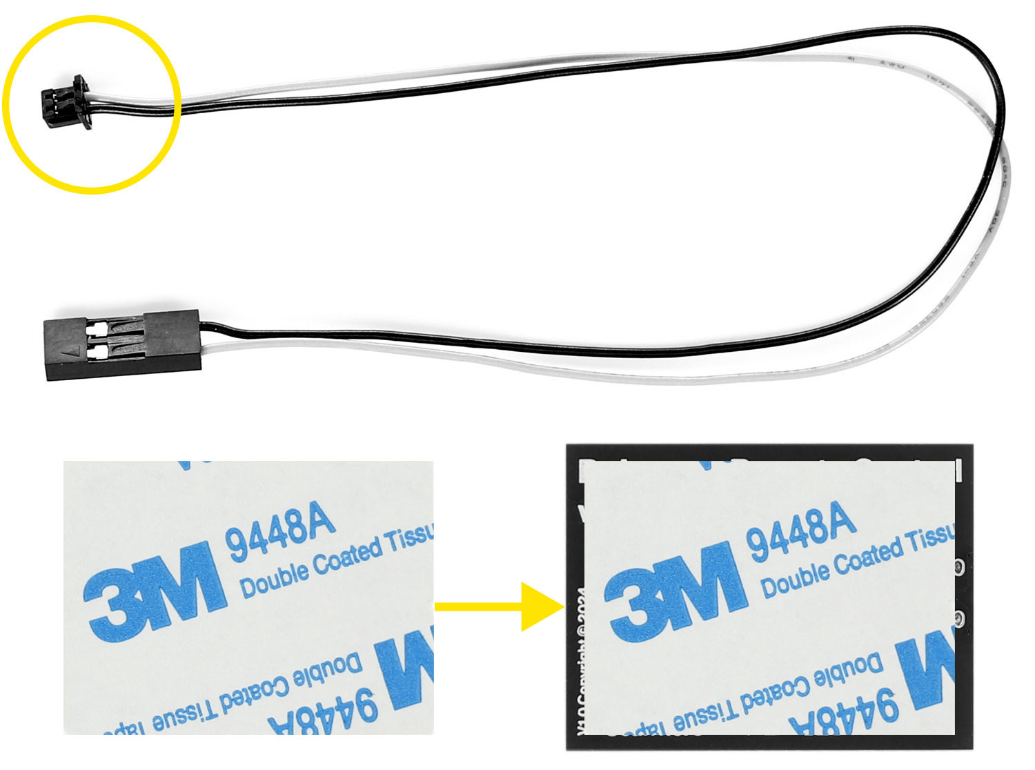
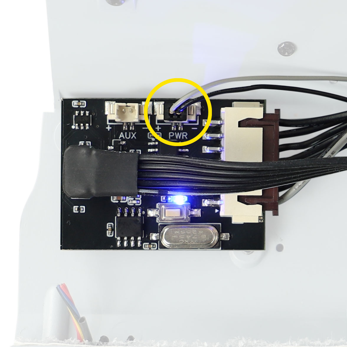
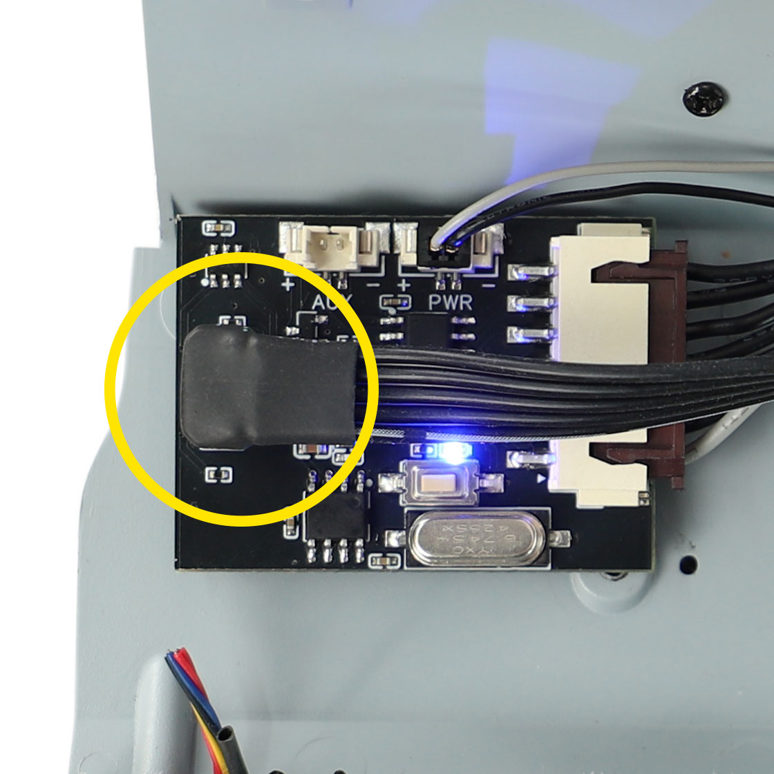
- Connect the other end of this cable to the socket on the Mike Lane DeLorean Remote Control circuit board labelled ‘PWR’.
- Apply the 3M foam adhesive foam to the back of the Mike Lane DeLorean Remote Control circuit board and affix into position on the left side of the rear of the bulkhead.
- Now connect the supplied USB extension cable to the USB-C port on the Mike Lane DeLorean Remote Control board, with the cable facing in towards the model.
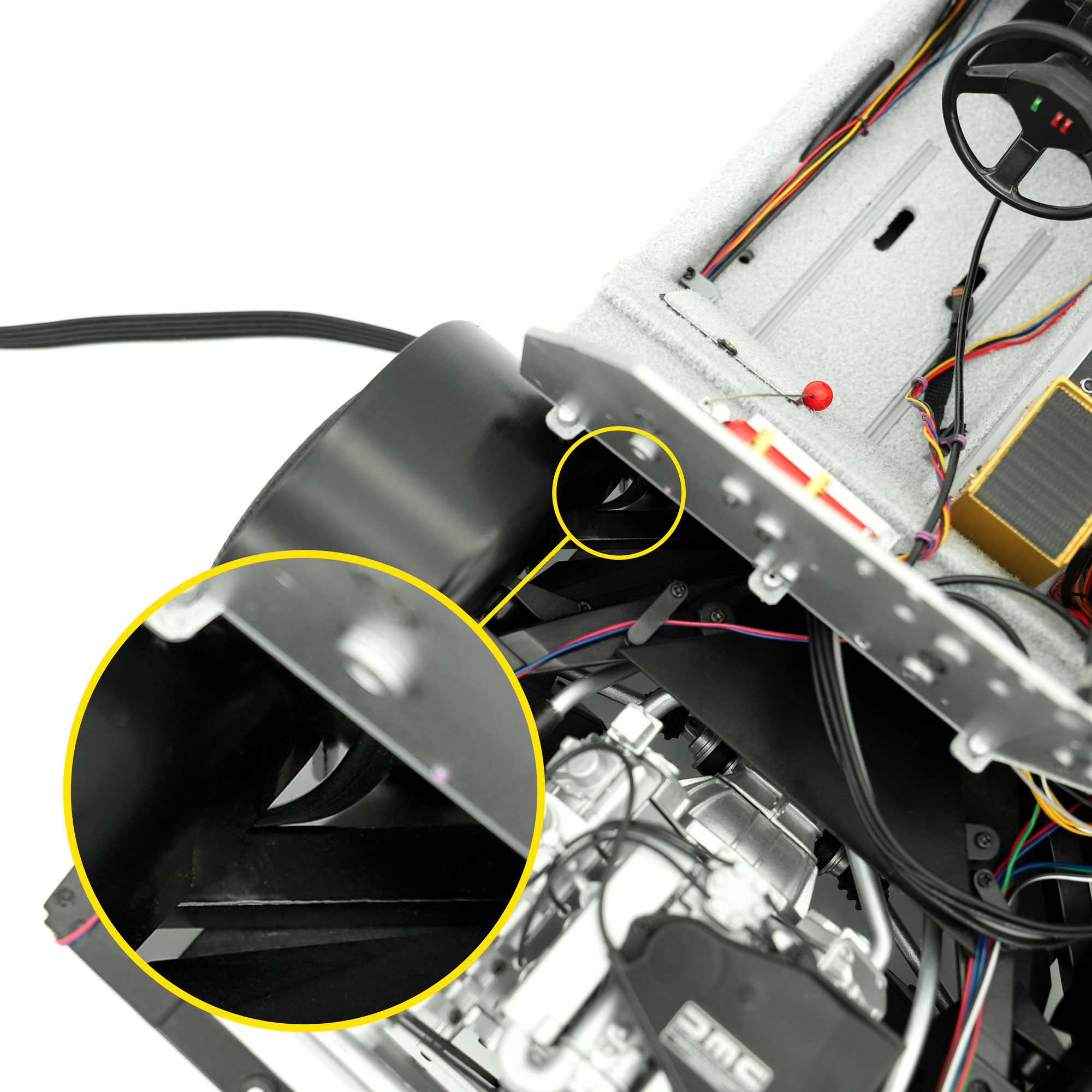
- We recommend feeding this cable down and through the chassis of the car via one of the rear wheel wells, but there are plenty of exit routes.
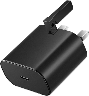
- You can now connect the braided USB-C cable to this extension and connect to a power source, such as a power bank, laptop, or USB-C adaptor.
- Test the operation of the board prior to replacing the floor and re-fitting the body.
Flexibility by design
The model will receive power via the provided slimline USB-C cable. The advantage of this is that the cable can be fed through any available hole in the model’s chassis, either exiting the left or right side, and can even be routed towards the front or rear of the car – the choice is yours! In many cases it can even be fed into the battery box and hidden away when not in use. No drilling and no glueing – making it totally reversible and giving you plenty of options depending on how you wish to display your model.
Two different remotes have shipped with this modification since it’s launch.
Please be sure to follow the correct binding instructions for the remote that you have received as they vary for each.
- Plug in the USB-C cable to a power source.
- The blue LED on the Mike Lane DeLorean Remote Control circuit board will light up dimly and extinguish after 10 seconds.
- Single press the programming button on the Mike Lane DeLorean Remote Control circuit board.
- The blue led on the circuit board will flash to indicate that the board is ready to receive remote codes.
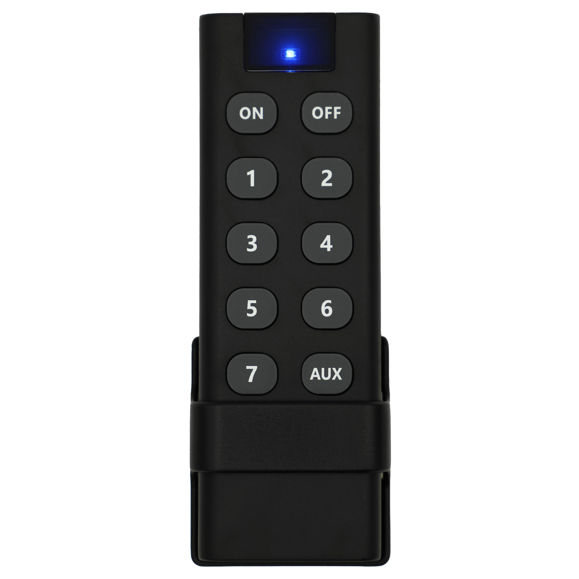
Black remote
Now press the buttons in this exact sequence, waiting one second between each press.
During this process the LED on the circuit board will light statically and blink each time a button is pressed to confirm receipt of the button code.:
- Button 1
- Button 2
- Button 3
- Button 4
- Button 5
- Button 6
- AUX
- ON
- OFF
Do not press button 7, it won’t be used.
You will see the car’s circuits come on one at a time. When you press the final button in the sequence (OFF) on the remote, the blue led on the circuit board will flash several times to confirm programming is complete.
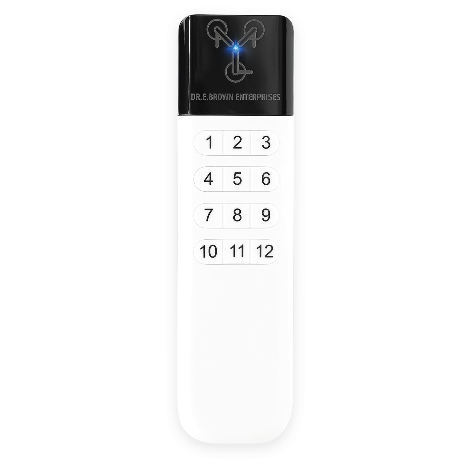
White remote
Now press buttons 1-9 on the remote control in sequence waiting one second between each press. During this process the LED on the circuit board will light statically and blink each time a button is pressed to confirm receipt of the button code.
You will see the car’s circuits come on one at a time. When you press button 9 on the remote, the blue led on the circuit board will flash several times to confirm programming is complete.
Syncing the power mod to the stock mainboard
Important: If binding a remote after power and connections to the stock mainboard have already been made, it’s important to power cycle the power mod by disconnecting power, leaving for 20 seconds and then reconnecting power. This ensures the power mod is correctly synchronised with the stock mainboard.
The buttons on the remote will now operate as follows:
| Button | Function |
| ON | Turns ALL circuits on |
| OFF | Turns ALL circuits off |
| 1 | Toggles all flux bands and reactor LED on / off |
| 2 | Toggles digital speedo LED on / off |
| 3 | Toggles Dashboard instruments on / off |
| 4 | Toggles Time Circuits, Flux and SID on / off |
| 5 | Toggles overhead panel lights on / off |
| 6 | Toggles Head & taillights, turn signals, engine bay and hood lights on / off |
| AUX | Toggles AUX power circuit on / off (for example any third-party mods) |
If you make a mistake during the coding or need to code a new remote, simply restart the process by disconnecting and reconnecting the USB power from the Mike Lane DeLorean Remote Control, and pressing the programming button again.
The buttons on the remote will now operate as follows:
| Button | Function |
| 1 | Toggles all flux bands and reactor LED on / off |
| 2 | Toggles digital speedo LED on / off |
| 3 | Toggles Dashboard instruments on / off |
| 4 | Toggles Time Circuits, Flux and SID on / off |
| 5 | Toggles overhead panel lights on / off |
| 6 | Toggles Head & taillights, turn signals, engine bay and hood lights on / off |
| 7 | Toggles AUX power circuit on / off (for example any third-party mods) |
| 8 | Turns ALL circuits on |
| 9 | Turns ALL circuits off |
If you make a mistake during the coding or need to code a new remote, simply restart the process by disconnecting and reconnecting the USB power from the Mike Lane DeLorean Remote Control, and pressing the programming button again.
The installation is now complete!
The AUX port
The AUX port on the Mike Lane DeLorean Remote Control circuit board provides a 5v output at 1amp (max) – switchable via the AUX button on the remote.
This port provides plenty of power and flexibility for potential customisations and future Mike Lane upgrades planned for this model – all controllable from the remote.
Can this power third-party modifications?
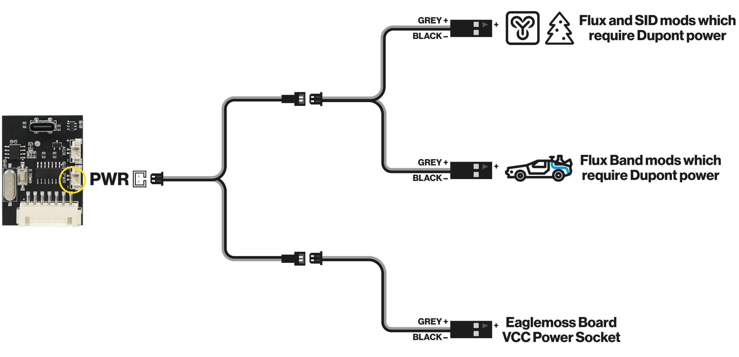
Yes! Whilst we have our own suite of electronic upgrades coming for this model, the Mike Lane Remote Control Power Mod also supports third-party modifications which require power via Dupont connectors. Please see the example wiring diagrams below.
Seriously cool mods incoming!
We’d like to take this opportunity to announce that we have our own electronic ‘time travel’ upgrades for the DeLorean Time Machine coming soon – trust us, you’re not going to want to miss them!
Polarity Warning
IMPORTANT: When connecting any third-party accessories using the supplied adaptor cables, ensure to check the polarity. The grey cable connects to positive and the black to negative.
Incorrect polarity will damage any connected circuit boards and modifications, voiding all associated warranties.
Use of third-party accessories and mods is entirely at the owners risk as not all third-party mods have been tested with this device.

