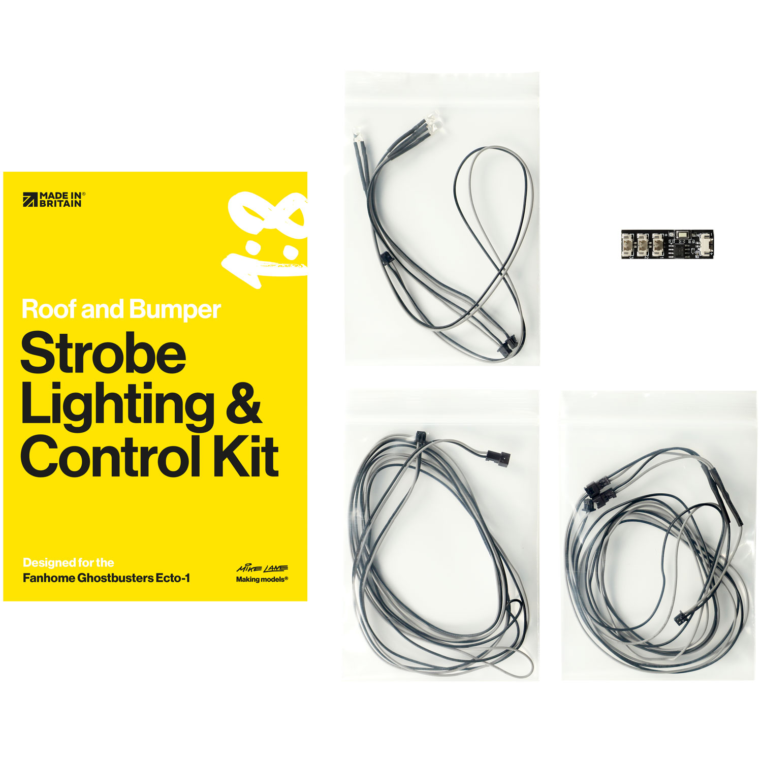
Designed for the Build the Ghostbusters Ecto-1 by Eaglemoss/DeAgostini/Fanhome.
You can begin the installation of this mod from Issue 2 of the build.
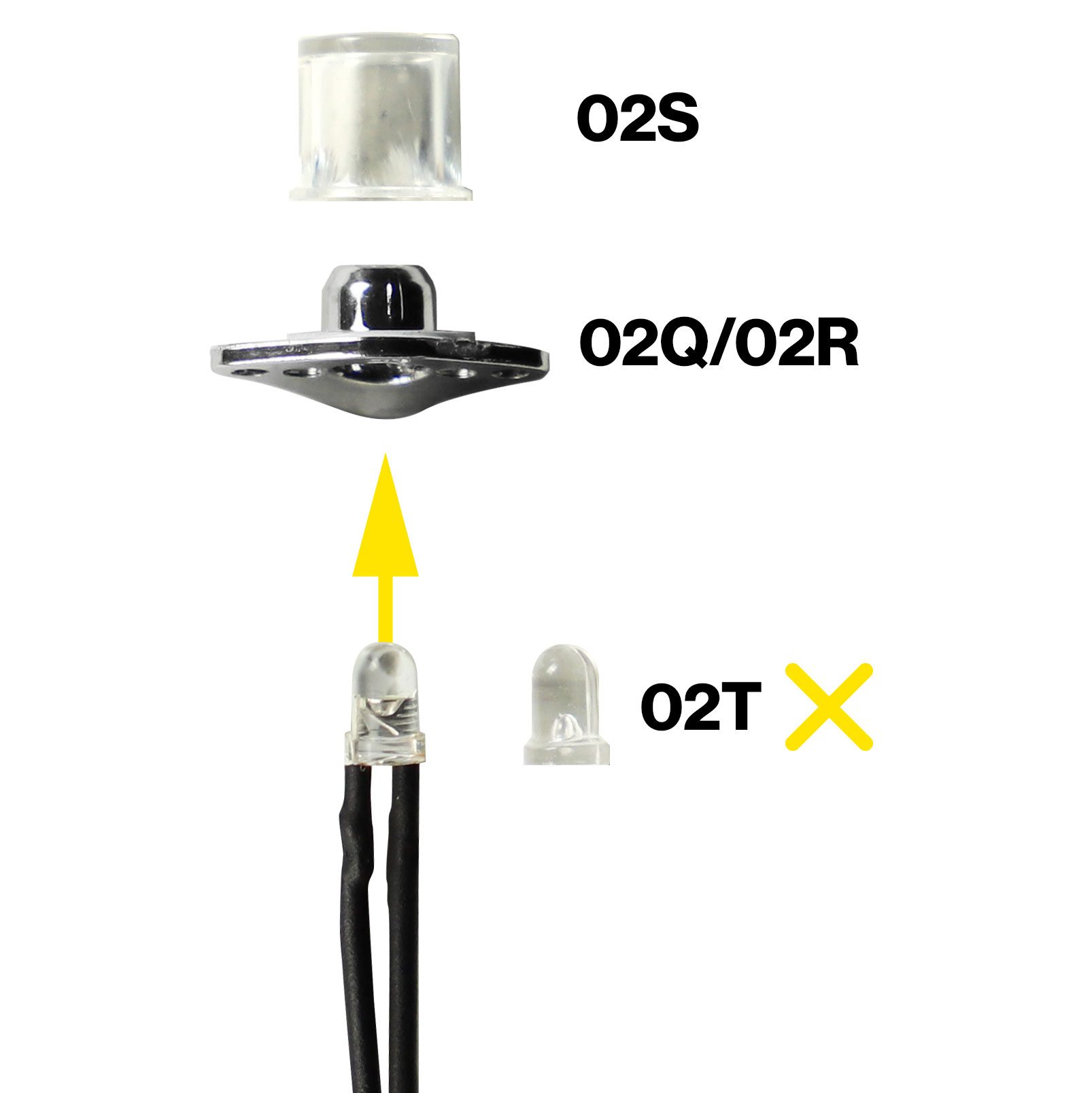
During the assembly of the front grille in Issue 2, you will need to install an LED into each of the two anti-collision strobe lights. The original anti-collision strobe light imitation bulbs (02T) are no longer required and should not be installed into the strobe light frames (02Q/02R) or should be removed if already installed.
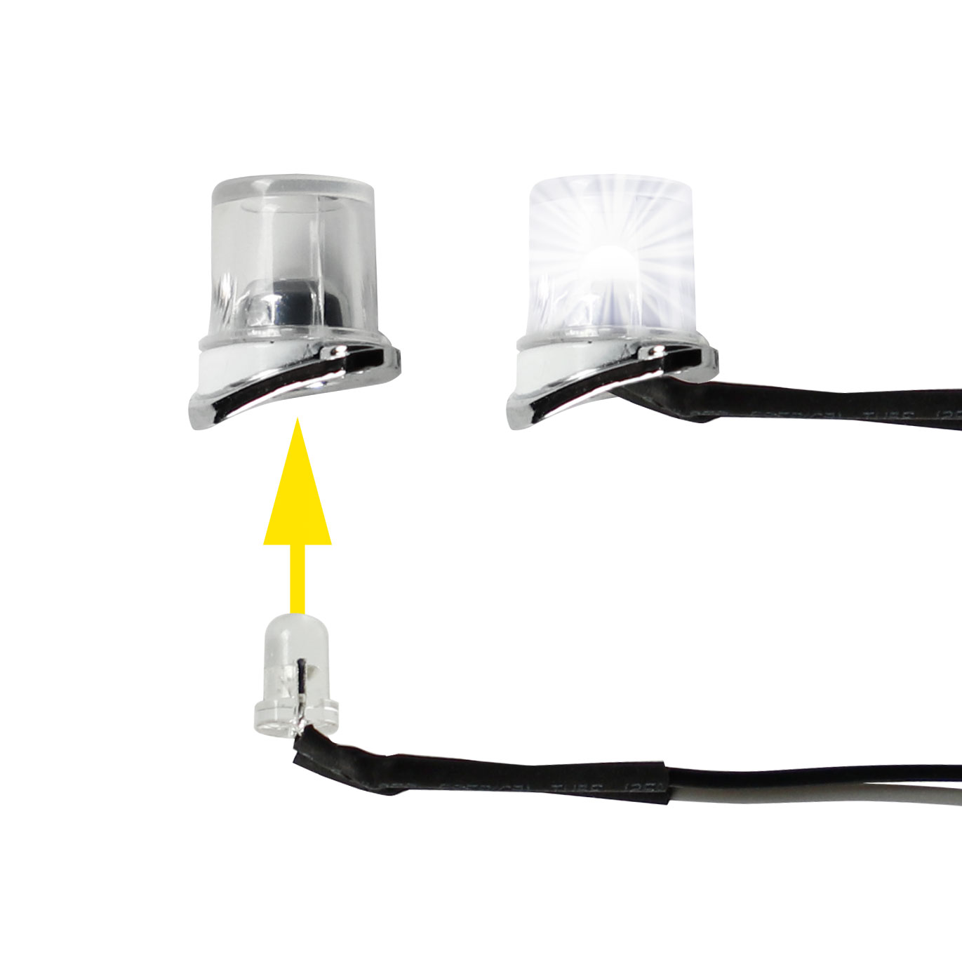
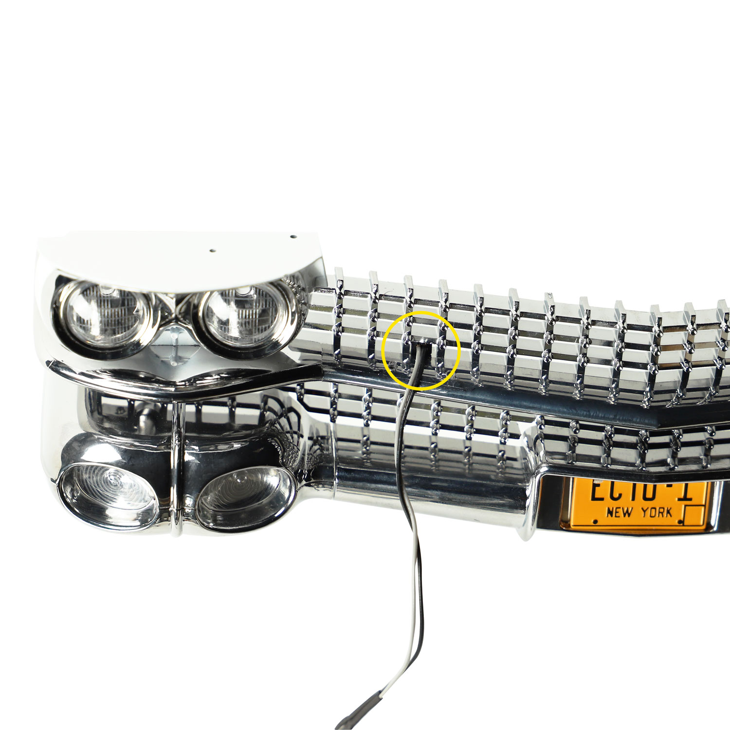
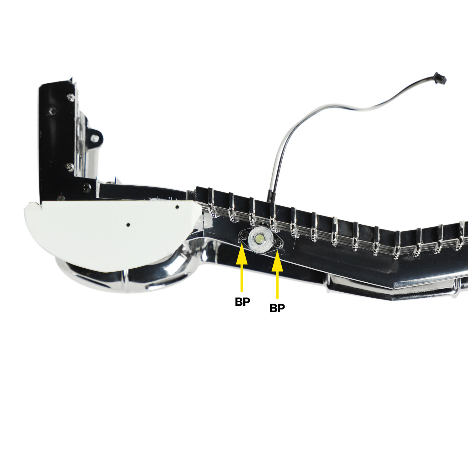
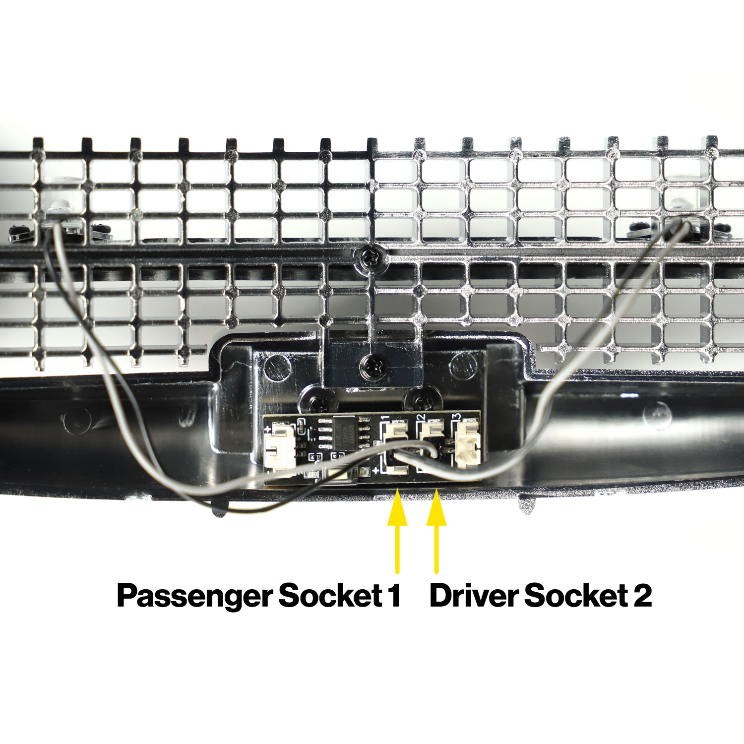
Take the two short strobe LEDs supplied within this kit, and insert them into the anti-collision strobe light frames (02Q/02R). They should fit snugly into the hole. Once installed, very gently bend the cables towards the rear of the frame (flat side) so that the cable is flat up against the underside of the strobe light frame. These cables will then pass through the radiator grille.
Then, using 2 x BP screws, securing each strobe light into the grille strip. This will clamp the LED cable down tight to the grille strip.
Take care not to over tighten the screws when attaching the bumper strobes as there is a risk you may restrict the strobe LEDs from receiving power. If they are screwed tight, unscrew two turns.
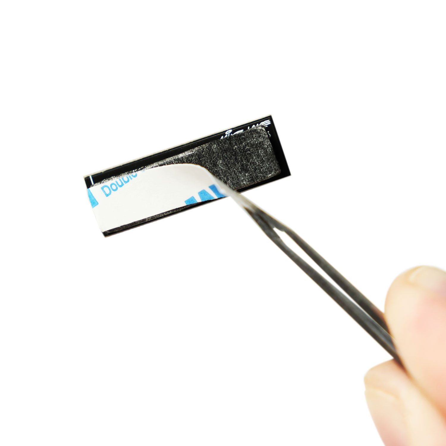
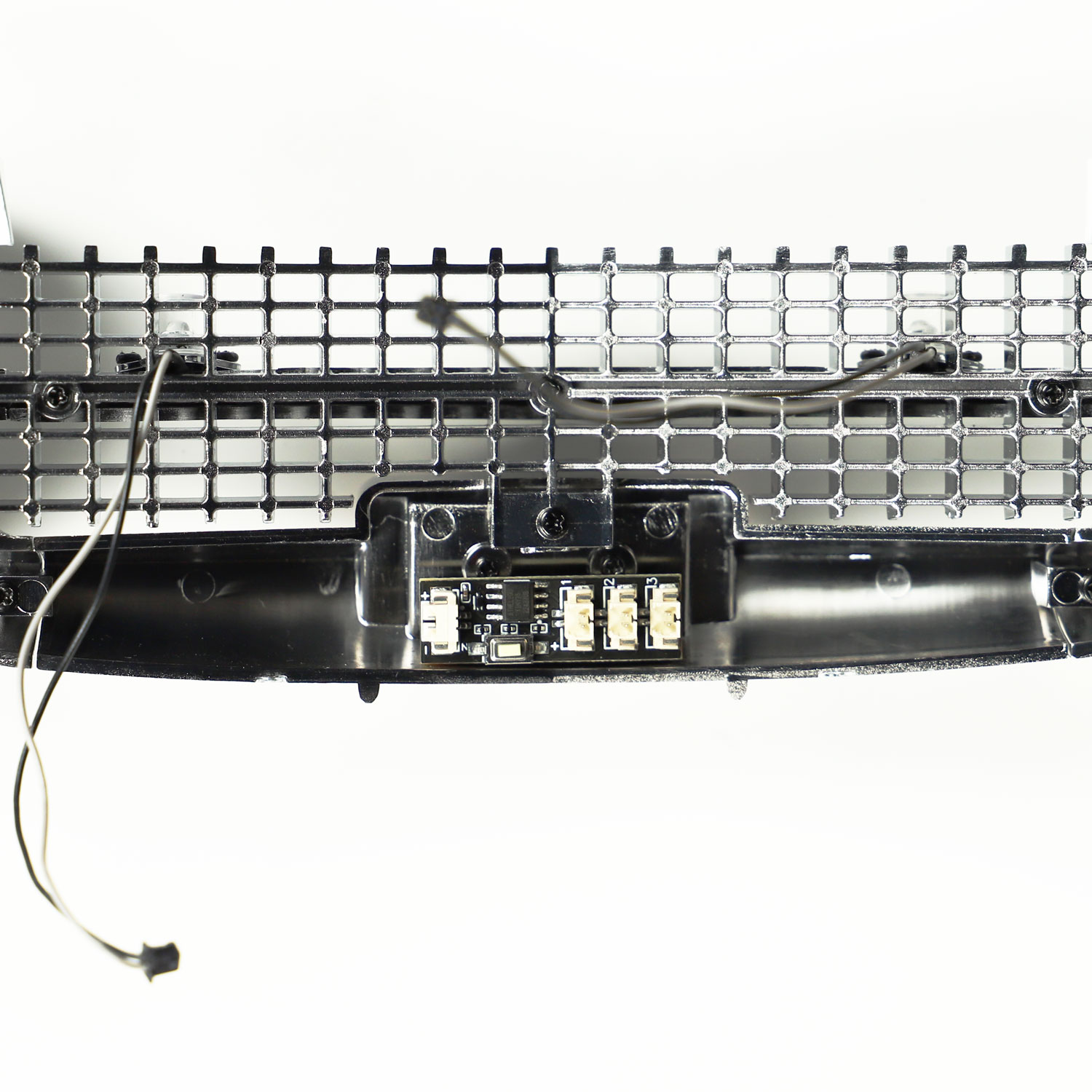
Attach to the inside of the front bumper as shown in the photo, with the button at the bottom and avoiding having the screws touching the back of the controller.
Positioning of the controller must match this placement exactly. It is the only safe position where you will be able to access the controllers mode button once the top half of the model is installed onto the chassis.
The plug on the end of this long cable needs to run to the front of the car, following the route of the existing cables detailed in stage 65 (beneath the driver-side footwell and towards the speaker and mainboard). This cable will provide power to the mini strobe controller.
Feed it over the top of the driver side wheel arch and into engine bay near to where the front bumper will be installed. It is advised that you secure this cable in place with small sections of black insulation tape.
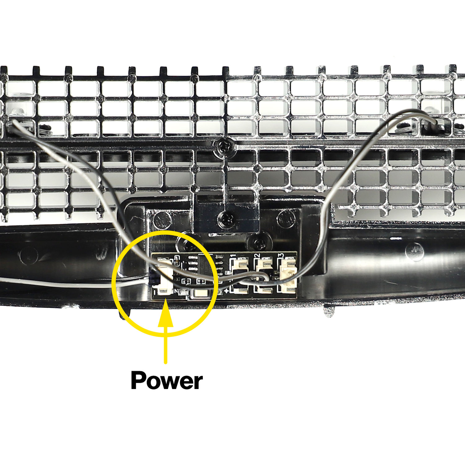
Plug this power cable into the socket on the left of the mini strobe controller labelled + –.
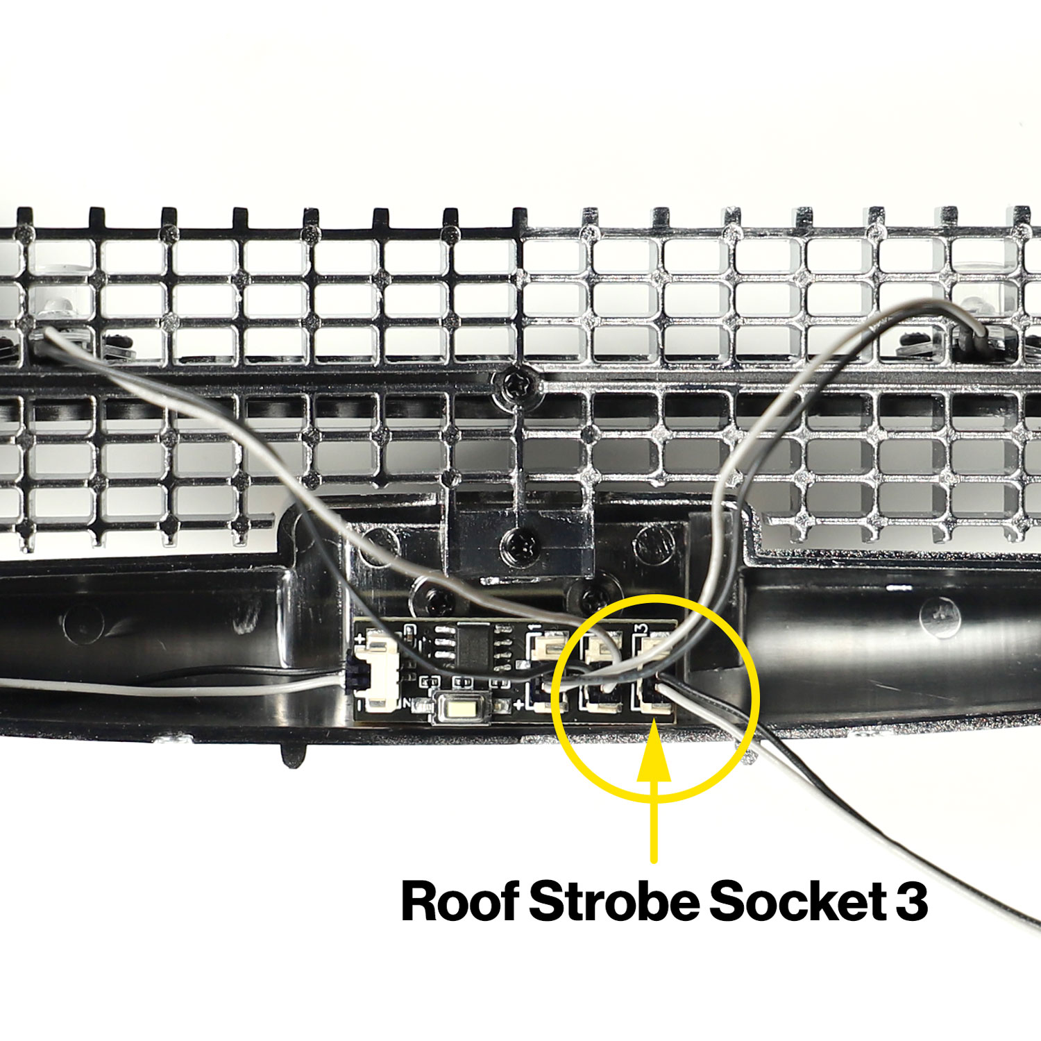
Plug the remaining long extension cable provided within this kit into socket 3 of the mini strobe controller. This will provide power to the roof strobe. Route the cable back along the car over the driver side wheel arch and along the floor with the existing cables.
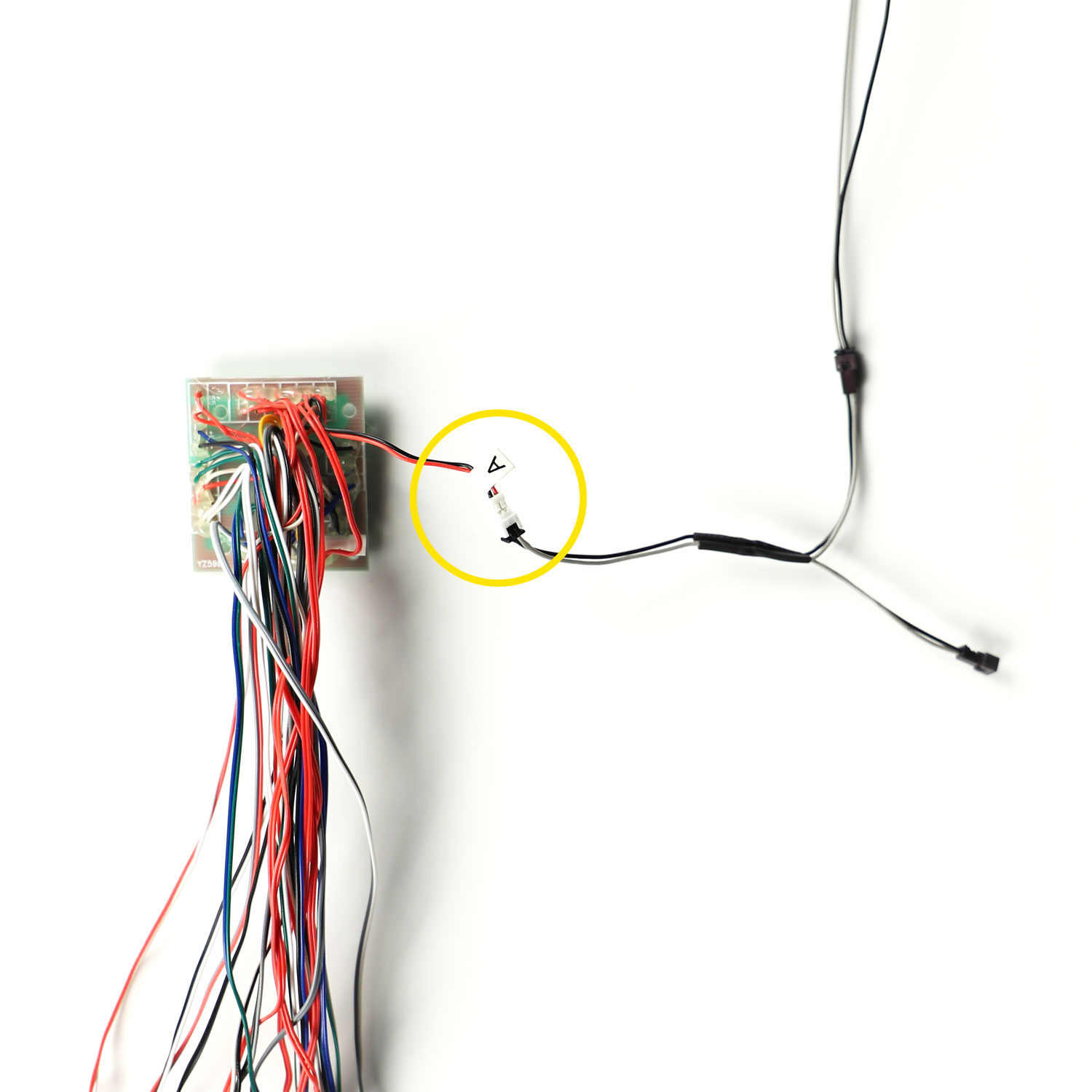
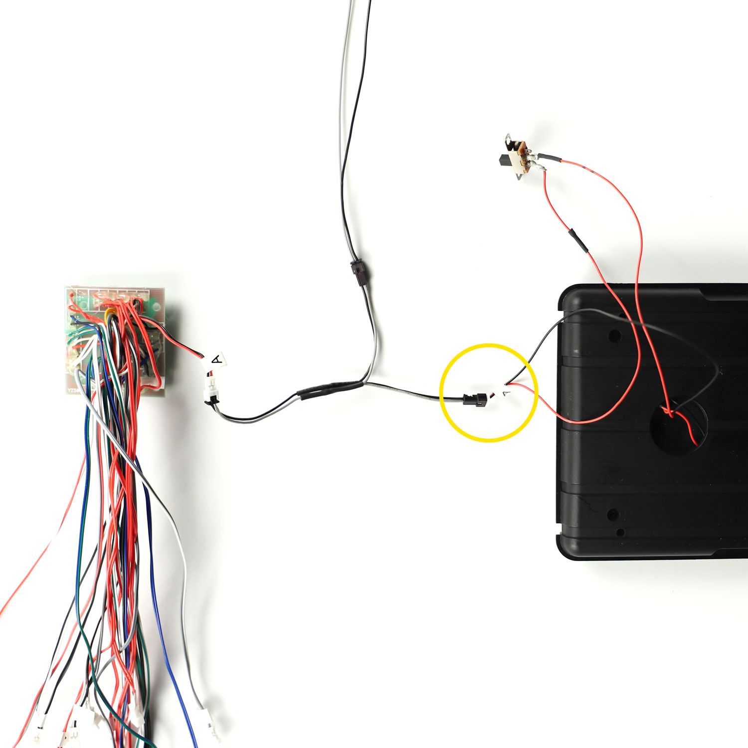
The socket end should end and be placed along with all the other stock cable connections just in front of the driver side rear wheel arch, ready for connection to the upper part of the car. It will connect to the stock extension cable marked ‘K’ which runs up the blue hose to the roof. (The cable marked ‘K’ on the original PCB will no longer be used).
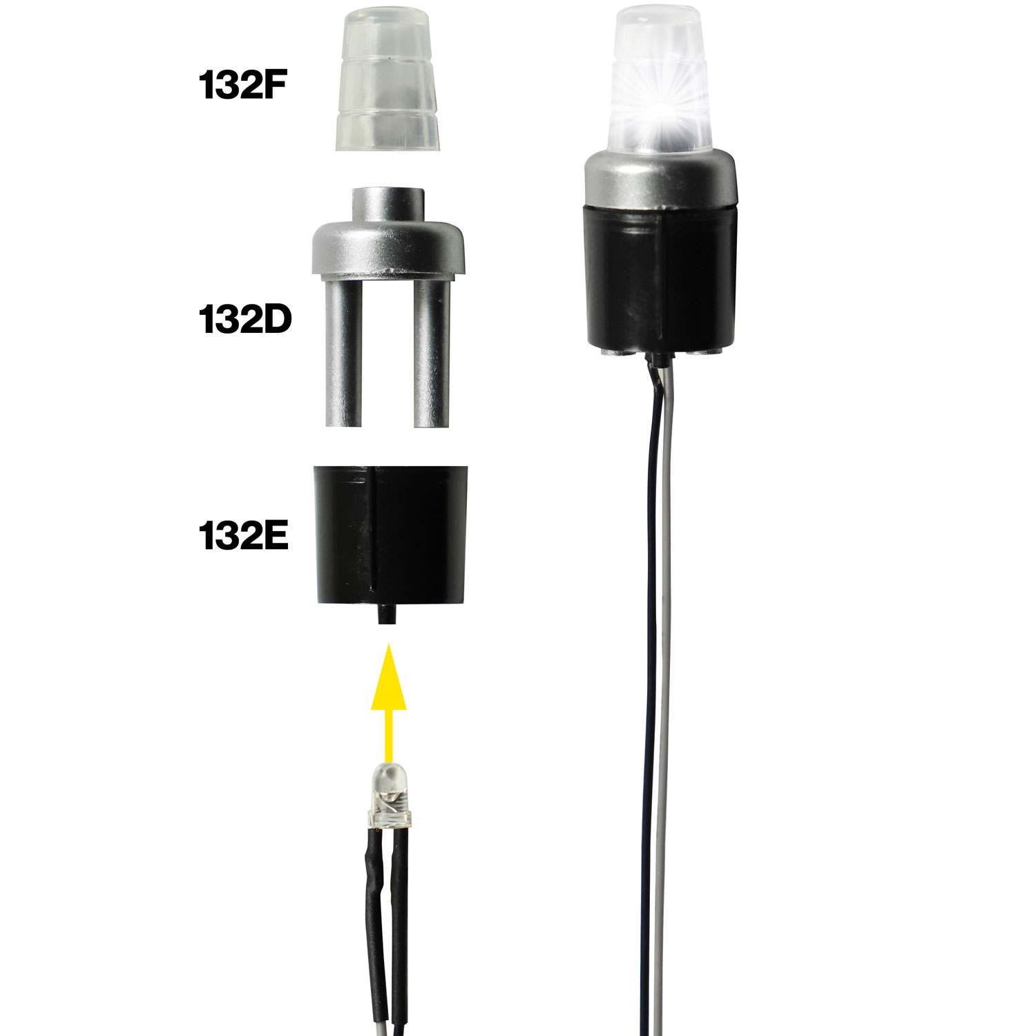
Fix to the roof frame lower (132K) with 2xTP screws – as per the instructions in issue 132.
During the installation of the roof box, this LED will be connected to the stock extension cable marked ‘K’.
The installation is now complete!
Please note: Each device has been fully tested before dispatch to ensure you have an issue-free installation.
The majority of questions we get asked are easily answered by carefully following the installation instructions above.
Facing issues?
If you experience any unexpected results, please check back over the instructions carefully, check all connections, then refer to the troubleshooting tips below if you need further assistance.
If you still need help, please contact us for assistance.

