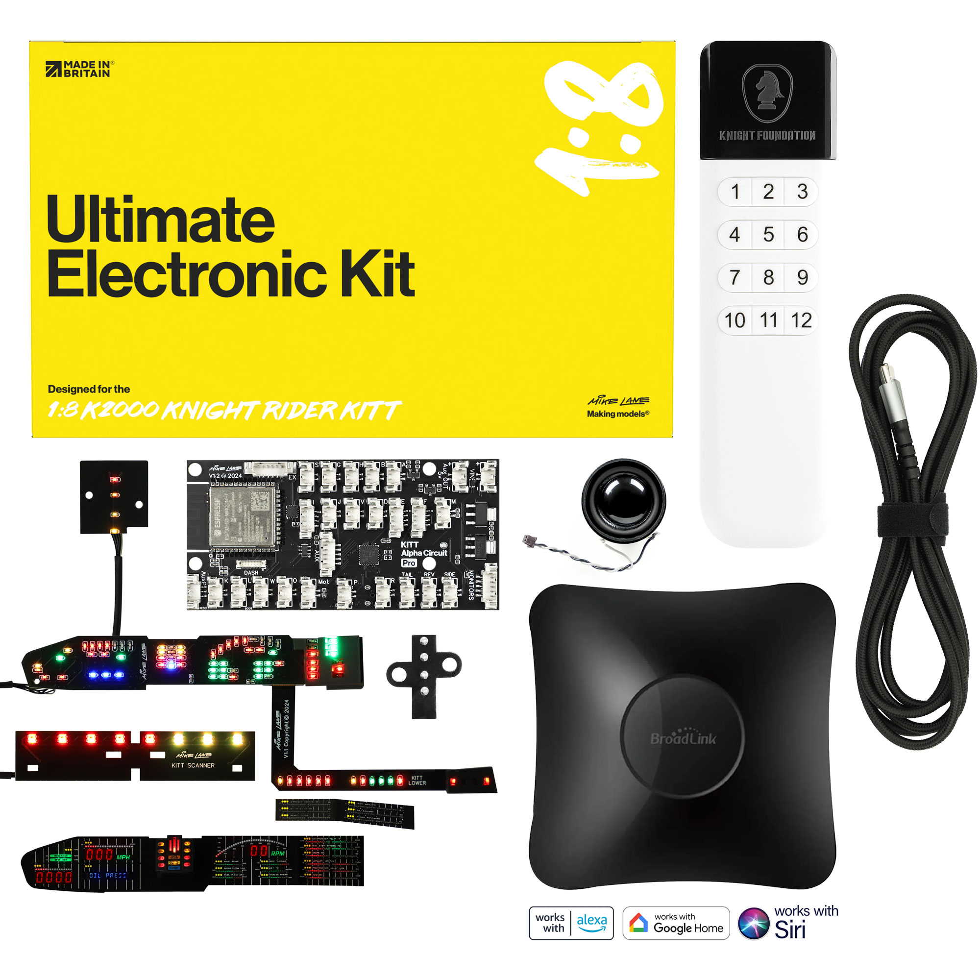
Designed for the Build the K2000 Knight Rider KITT from Fanhome/DeAgostini/Altaya.
The simple rule
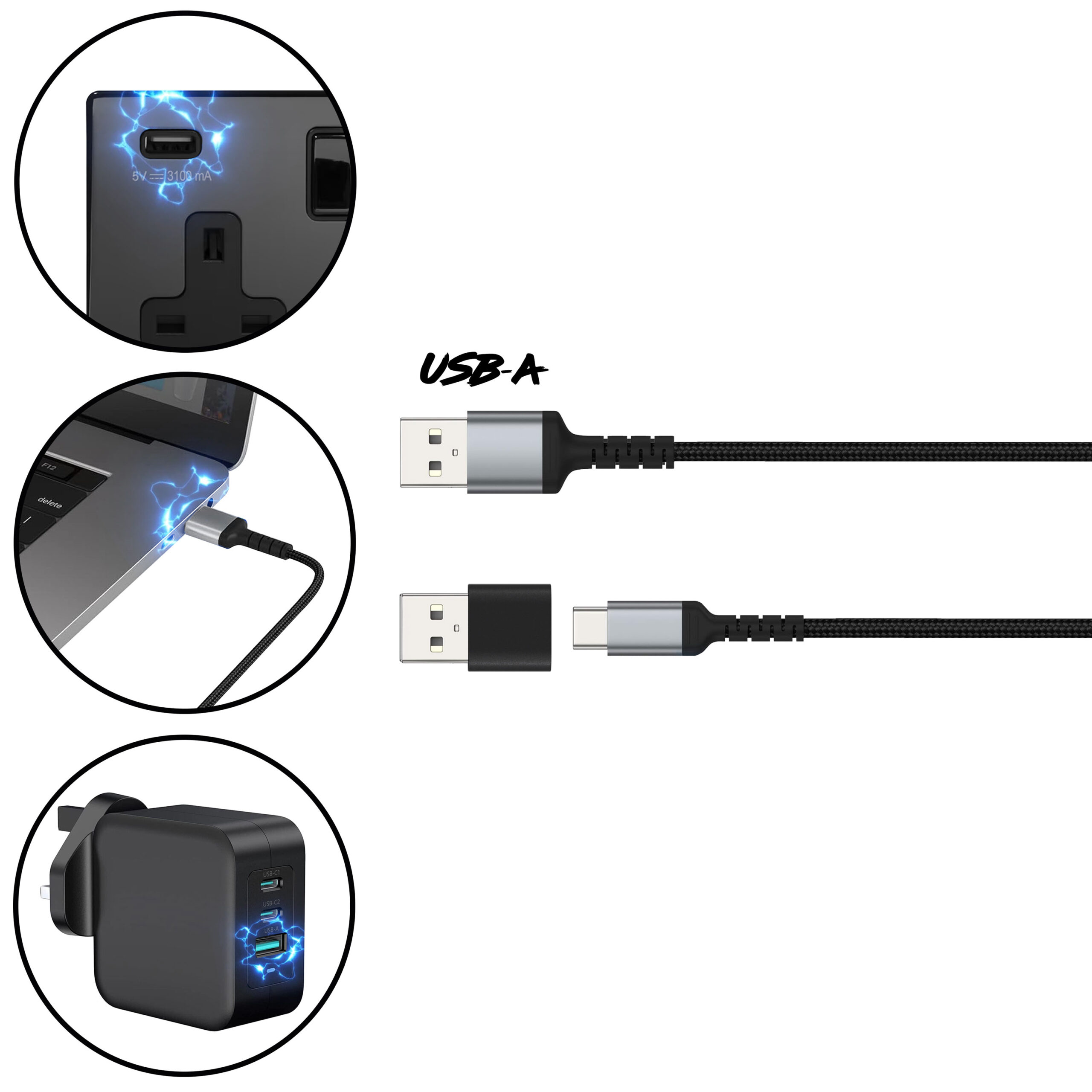
Stick to USB-A for safe, stable 5V power.
Only use direct USB-C if you know the adaptor outputs a fixed 5V.
You can power your model using any standard USB-A power sources, including:
In-wall USB sockets rated at 5V (e.g. 5V 3.1A/3100mA is ideal)
USB ports on laptops, PCs or Macs (most supply a fixed 5V)
USB power banks with a fixed 5V output
Powered USB hubs that provide a fixed 5V output
Or a dedicated USB power adaptor:
Mains power adaptors with USB-A port that provide a fixed 5V output
If your kit includes only a USB-C cable, you’ll need either:
- a dedicated 5V 2A USB-C power adaptor, or
- a USB-C to USB-A adaptor to connect to standard USB-A sockets (such as those found in wall outlets, PCs, or USB power adaptors).
Never attempt to power the model via any other method, including:
Third-party power mods or alternative power sources.
Multiple power mods at once
This product is a complete power mod solution. Connecting more than one power mod together is dangerous and may cause serious damage or fire risk. If another mod is already installed, remove and fully disconnect it before starting.
The existing battery box or batteries.
This power mod replaces the battery system entirely. Connecting both may cause malfunction or damage..
Fast chargers, smart chargers, or variable-voltage adaptors when using USB-C
If connecting directly using USB-C, avoid using adaptors with technologies such as USB Power Delivery (PD), Quick Charge or Fast Charge, which can output higher voltages (e.g. 9V, 12V, 20V). If proper voltage negotiation doesn’t occur, the adaptor could deliver too much power and damage the circuit. Using USB-A sockets however is usually safe and they almost always output a fixed 5V, which makes them much safer for your power mods.
Technical information
This product requires a stable 5V (max) 2A (min) power supply to function reliably.
To clarify:
- 5V is the maximum voltage — anything higher may damage the product.
- 2A is the minimum current — higher current (e.g. 3.1A/3100mA) is perfectly fine. The device will only draw what it needs.
So, for example, a wall socket with USB-A connection rated 5V 3.1A is ideal and completely safe to use.
As tempting as it may be, do not plug power into the new components just yet, there is some preparation to do first.
Step 1 Setting the language
The kit includes a MicroSD card containing all sound files and a settings file named config.txt.
You’ll find the card pre-installed in the MicroSD extender cable.
Preset languages
You should see a label on the Ultimate Electronic Kit box and/or the MicroSD package showing the preset language/radio region: UK (UK-EN), US (US-EN), FR (French), or DE (German). If this matches your preference, no action is needed—simply skip this step.
For orders from other countries, the default preset is UK-EN.
To change the language, follow these steps:
- Insert the MicroSD card into a card reader on your PC or Mac.
- Open the config.txt file on the card.
- Locate the line starting with lang: and change it to your preferred language code (e.g. lang:FR, for French).
- Save the file.
Please note that the values are case sensitive.
The following language codes currently supported are as follows:
- lang:EN, – UK & US English
- lang:FR, – French
- lang:DE, – German
Support for more languages are planned for the future via downloadable language packs from our website.
Please note
The config.txt file must follow the exact format shown—any deviation may cause errors.
If you ever need to restore the default UK-English settings, use the following factory configuration:
mode:presentation,lang:EN,identity:KITT,mute:0,monitoraudio:1,vol:14,lights:0,foglights:1,popup:0,markers:1,interior:0,dashstatus:1,enginestatus:0,scanpattern:1,shortscan:0,scanner:0,auxbutton:1,auxstatus:1,radiostation: ice-sov.musicradio.com/Heart80sMP3,
The values in config.txt are case-sensitive, so be sure to match the exact capitalisation as shown—incorrect casing may prevent the device from working properly.
Only edit config.txt where this guide specifically instructs you. Changing or deleting other values may cause the device to malfunction.
All adjustable settings are detailed later in the ‘Adjustable Settings’ section. These are typically changed using the remote control—or via the upcoming mobile app—so manual editing is rarely needed.
Step 2 Getting to know the Alpha Circuit Pro
Introducing the Alpha Circuit Pro – KITT’s upgraded mainboard. It supports all stock electronics while adding a host of new features and enhancements, all within the original footprint.
For ease of use, all sockets are named identically to those on the stock board.
Identifying your Alpha Circuit Pro
There are two versions of the Alpha Circuit Pro currently in circulation.
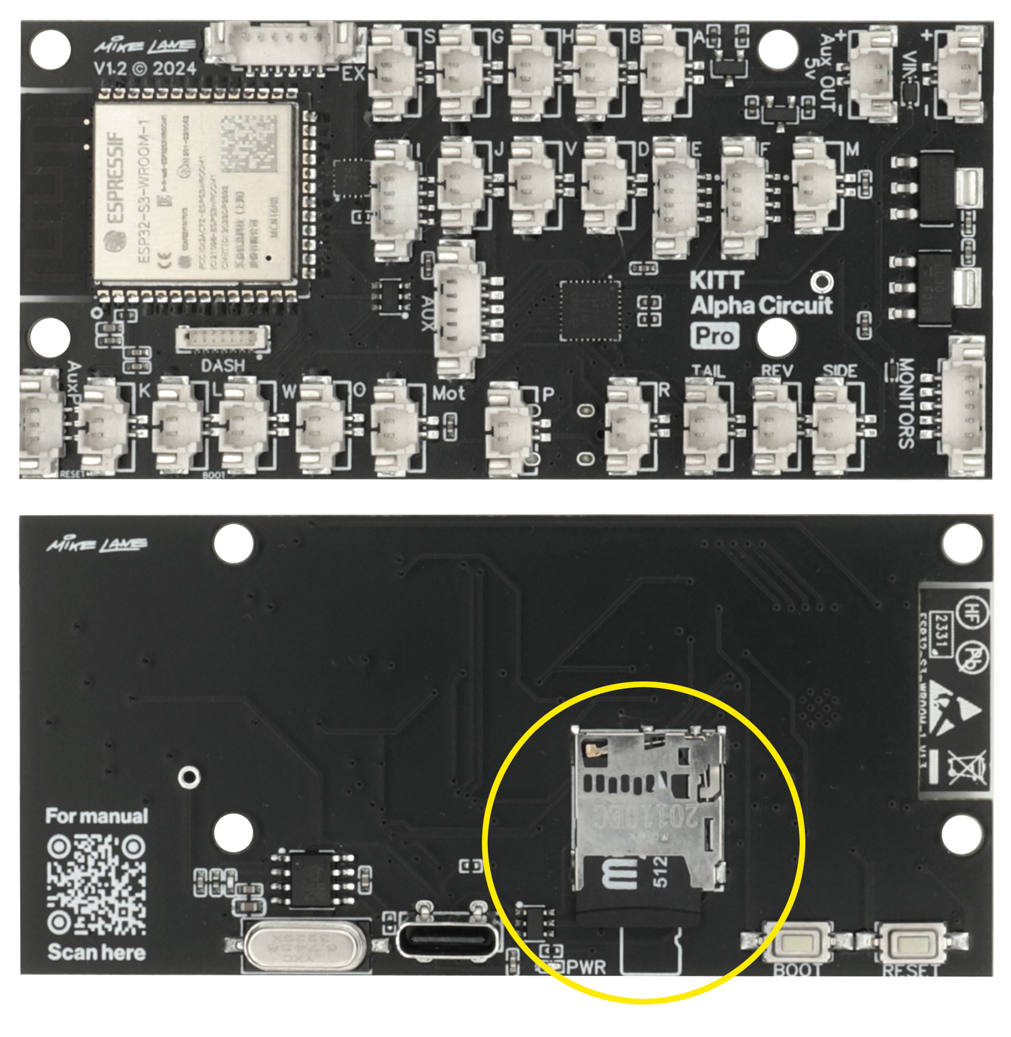
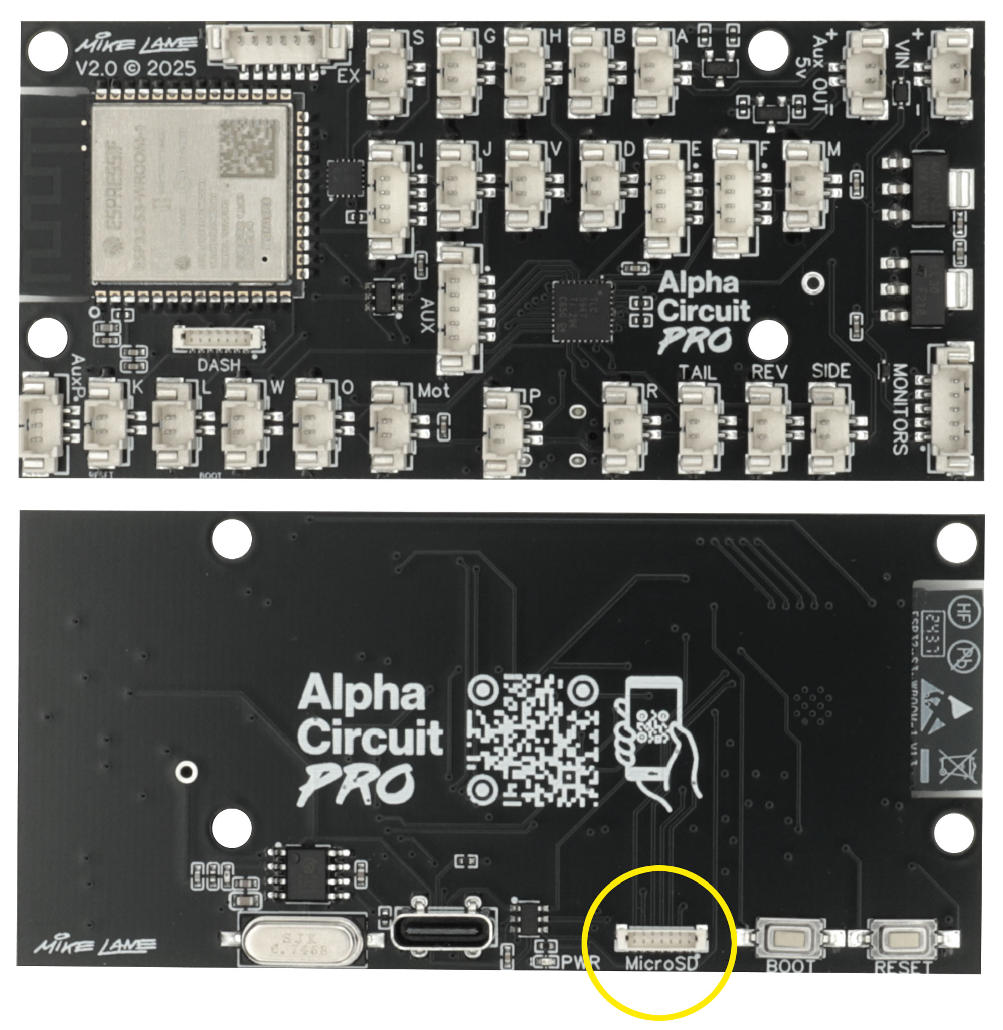
Both are functionally identical, with only minor differences in socket layout and labelling. You can identify which one you have by the version number printed in the top left corner (V1.2 or V2.0).
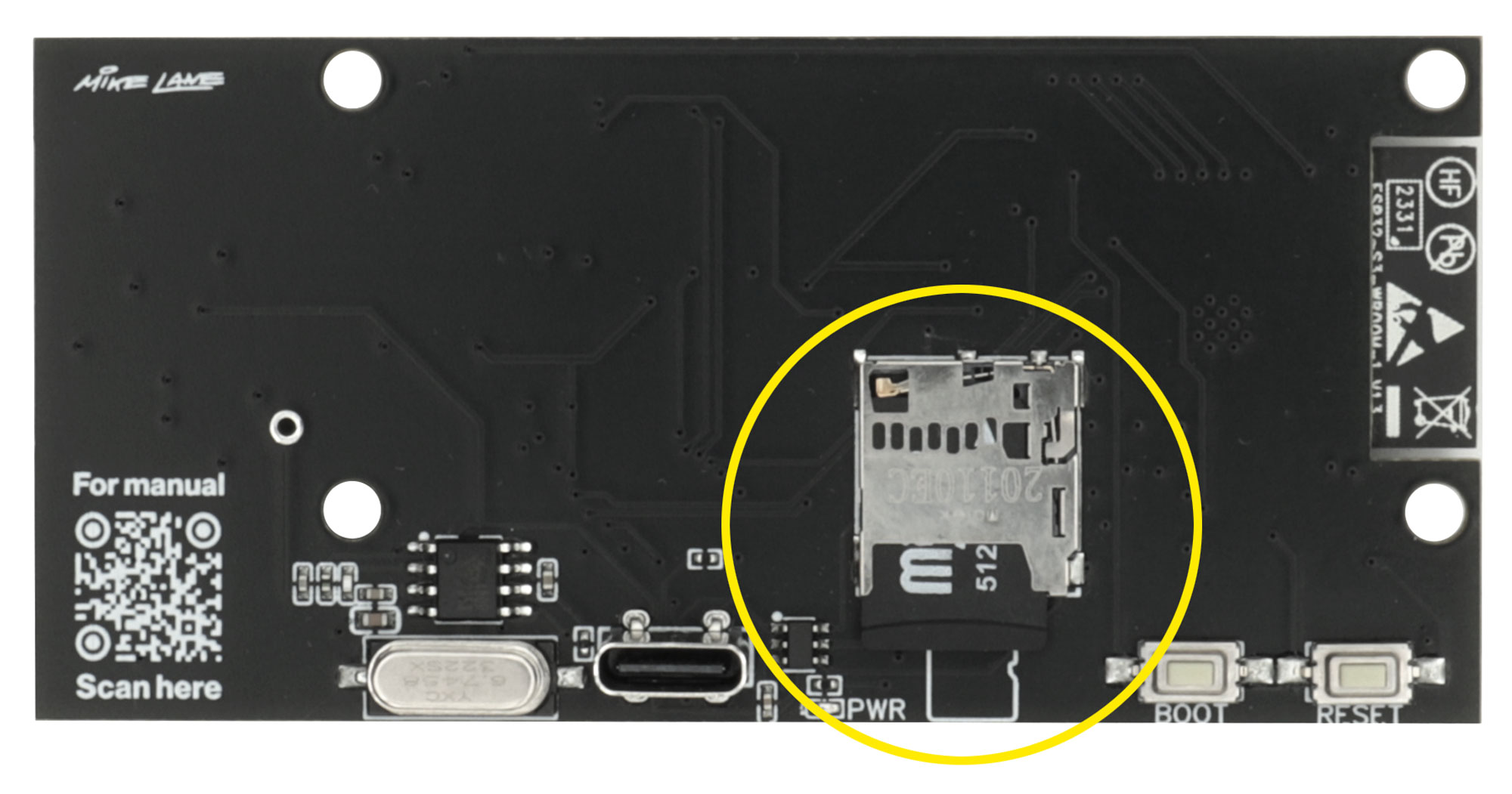
The main difference is that later boards (V2.0) have a MicroSD socket on the rear to accommodate a separate MicroSD reader (included in the kit), rather than having the reader built directly onto the board. This design simply makes repairs easier if the MicroSD port is ever damaged—but functionally, it performs exactly the same.
Please refer to the connection diagram below that matches the version of the Bat-Circuit you have:
Carefully remove the Alpha Circuit Pro from its packaging, taking care not to damage any components.
One side houses all the sockets for connecting to KITT, while the other features the USB-C power socket, MicroSD card slot, and RESET/BOOT buttons. These buttons are for support use only and shouldn’t be pressed during normal operation.
The underside buttons and sockets are accessible via KITT’s battery compartment once assembled.
Step 3 Identifying the new cables and LEDs
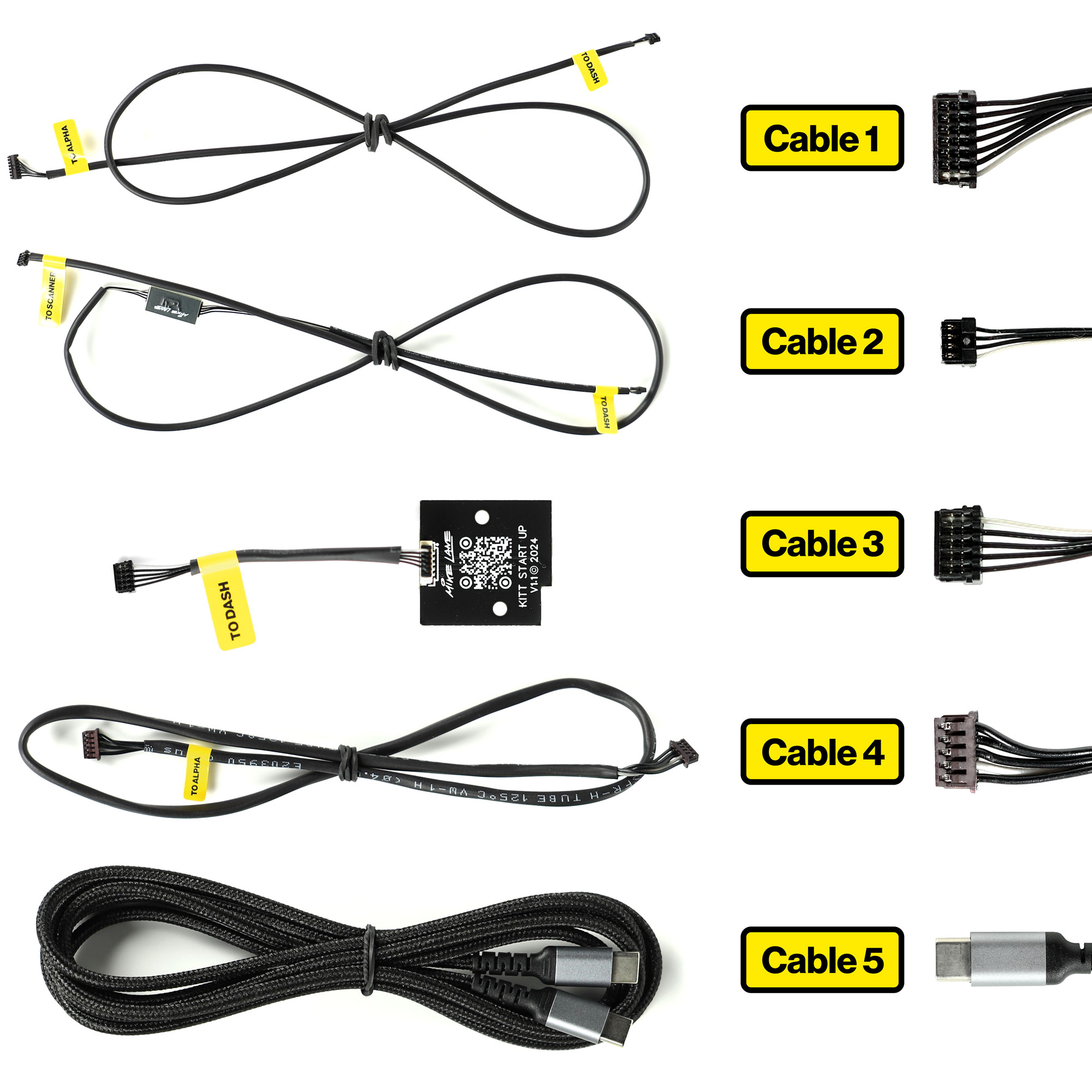
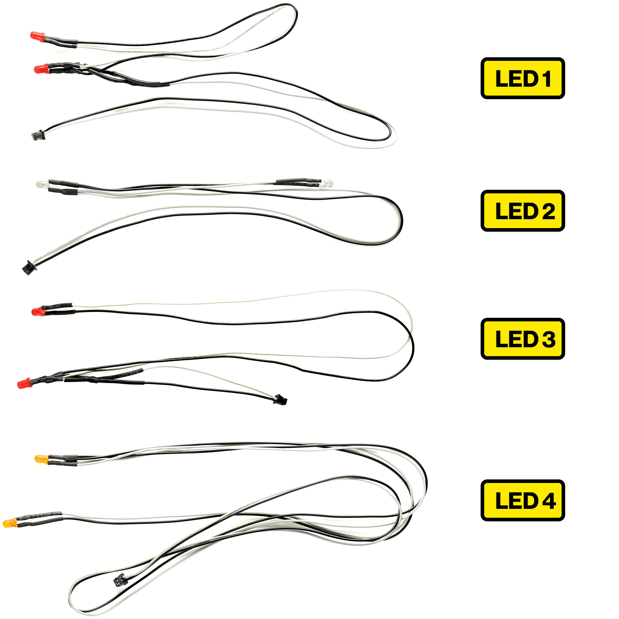
There are 10 unique cables and 4 types of LED included within the Ultimate Electronic Kit.
Refer back to this section for help identifying each during installation.
Cables
- Cable 1 – This connects the electronic dashboard (dash) to the Alpha Circuit Pro
- Cable 2 – This connects the dash to the new scanner
Cable 2 includes a mini connector board. This allows you to easily disconnect the dash and interior from the rest of the model during installation/disassembly if required. When disconnecting, it’s recommended to leave one end of the board connected to a cable to avoid losing the board.
- Cable 3 – This connects the start-up panel to the dash, and comes pre-connected to the start-up LED panel.
- Cable 4 – This connects the monitors to the Alpha Circuit Pro.
- Cable 5 – This 2M Braided USB-C cable powers the entire model.
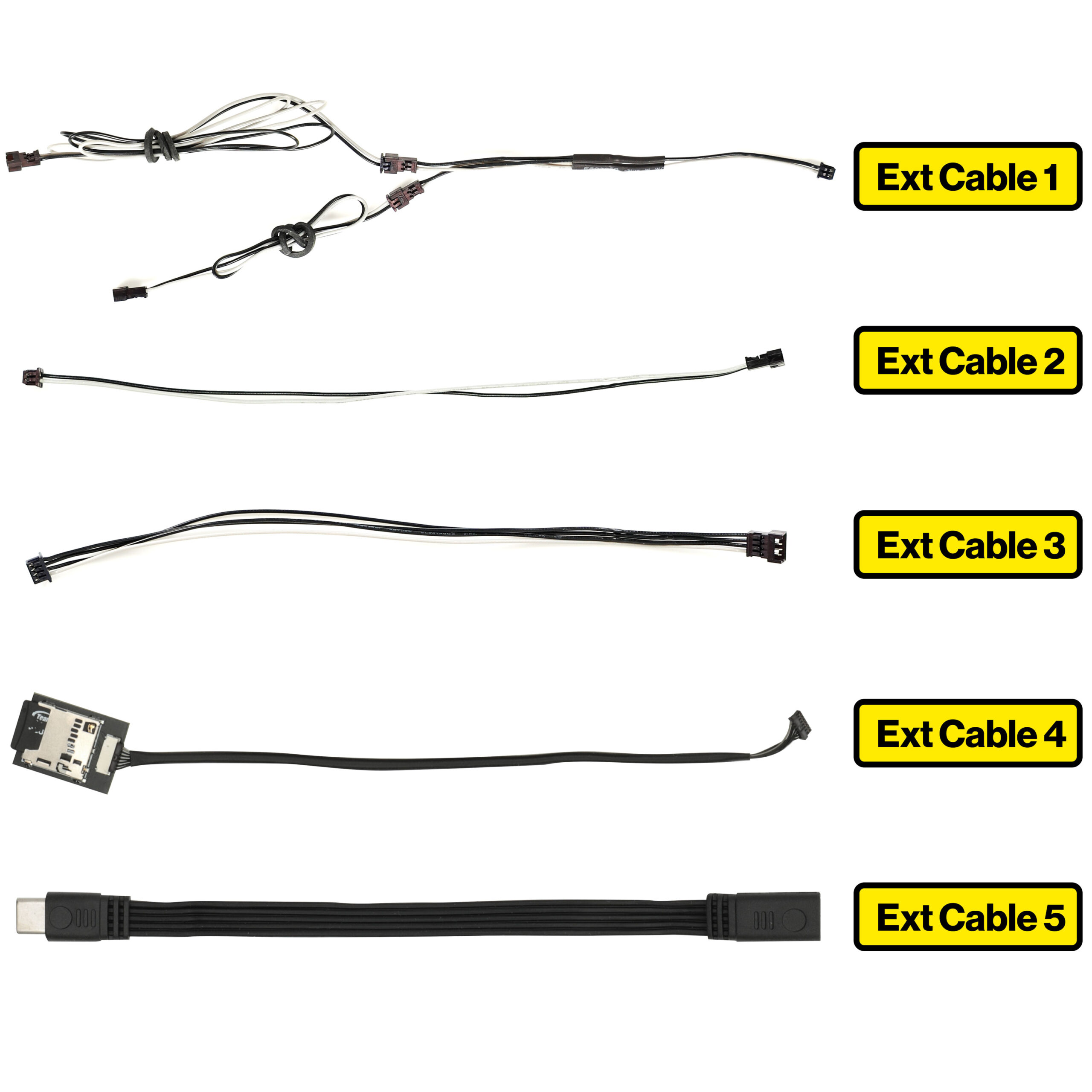
Extension Cables
- Extension Cable 1 – This splits and extends power to the front and rear side marker lights.
- Extension Cable 2 – These (x3 included) extend power to the new reversing lights, brake lights and one for the lower centre console light cable V (44I).
- Extension Cable 3 – This extends the floor lighting cable F (44A) to the Alpha Circuit Pro.
- Extension Cable 4 – Extends the MicroSD port into the battery compartment. Included only with later versions of the Alpha Circuit Pro (V2.0 and above).
- Extension Cable 5 – This extends the USB-C power port to the battery box for easy access.
Step 4 Preparing the Electronic Dashboard
Carefully remove the electronic dashboard from its packaging, taking care not to damage the sockets on the rear or the LEDs on the front.
There are three cables that must be connected to the dashboard before installation. Take extra care to connect them correctly and gently, as the connectors are small and delicate. Forcing them or pulling on the cables can damage the electronics—always grip the plug itself and ensure proper alignment before insertion.
These are:
- Cable 1 – This connects the dash to the Alpha Circuit Pro
- Cable 2 – This connects the dash to the new scanner
- Cable 3 – This connects the dash to the upper start-up board
Warning: Handle with care
The connectors are very small and delicate. Always insert them gently and the correct way up—never force them.
Each plug is keyed to fit only one way, but their small size makes them easy to damage if misaligned. Avoid pulling on the cables—always remove by gripping the plug itself. A magnifying glass may help with alignment.
Rough handling or incorrect insertion may result in damage to the connectors or surrounding components, so take your time and proceed carefully.
Cable 3 – Dash to the upper start-up board
This cable is pre-installed to the upper start-up LED panel. Take the lose end of the cable labelled ‘TO DASH’. This end of the cable connects to the rear of the electronic dashboard – to the socket labelled ‘TOP’. Ensure that the grey cable is on the LEFT as shown.
Step 5 Preparing the car
New builds
If you’re a new subscriber or have yet to start building KITT, excluding some early parts listed below, you can build up to Issue 42 before the Ultimate Electronic Kit comes into effect.
You can also exclude the following parts from the dashboard:
Stage 04:
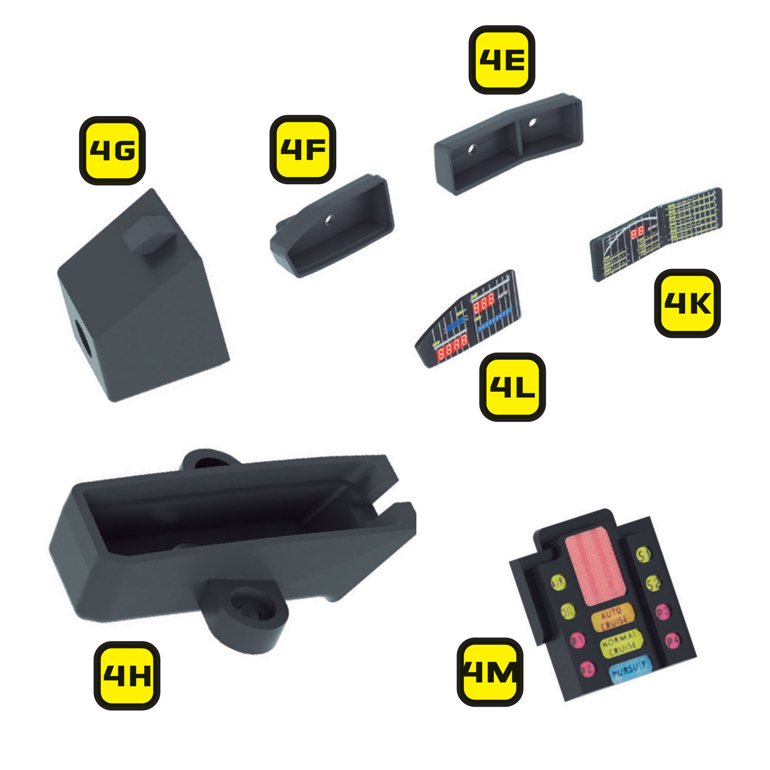
- 4E – Right instrument housing
- 4F – Left instrument housing
- 4G – K.I.T.T voice box
- 4H – Start-up panel bracket
- 4K – Right instrument panel
- 4L – Left instrument panel
- 4M – Front panel of K.I.T.T voice box
These components will not be reused.
If you have purchased the Mike Lane Dashboard Monitors, then you can also exclude:
Stage 04:
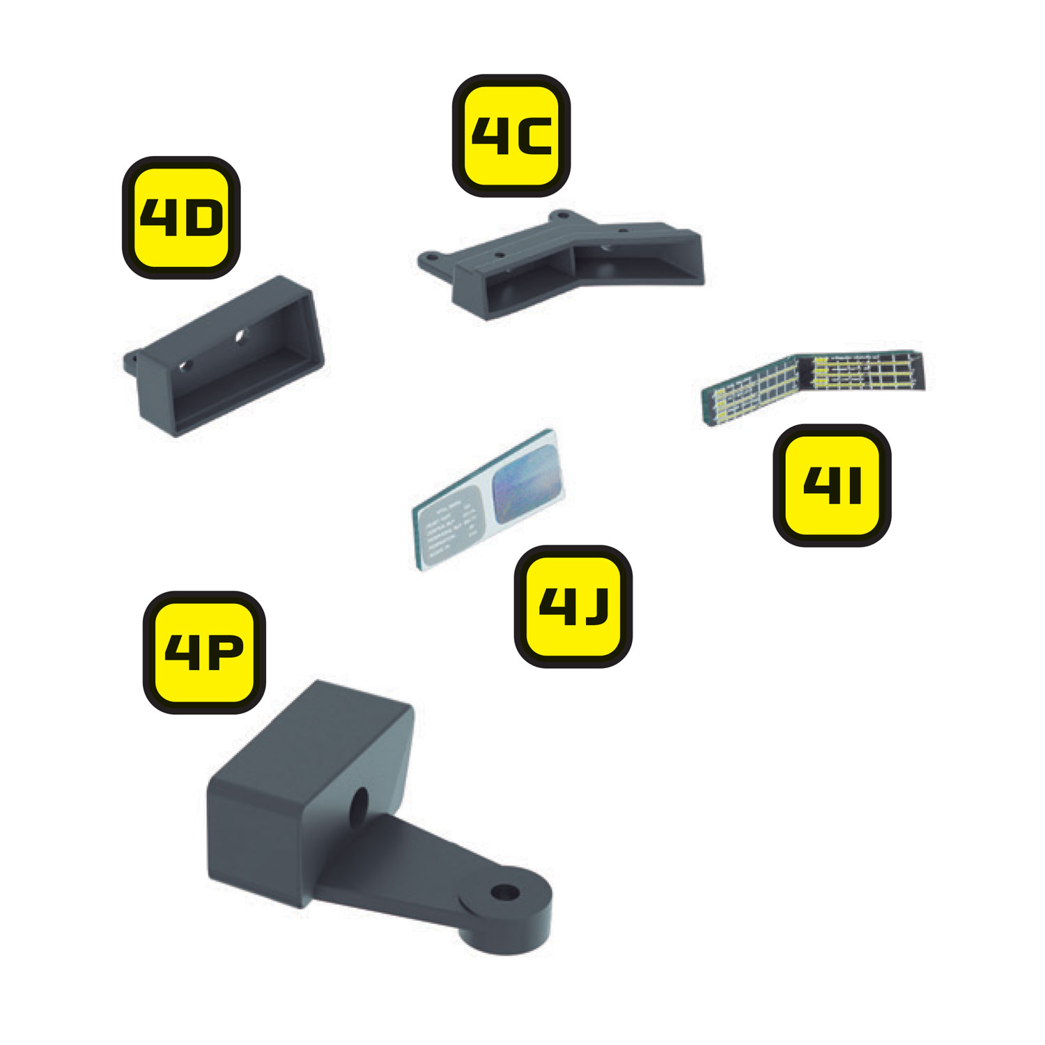
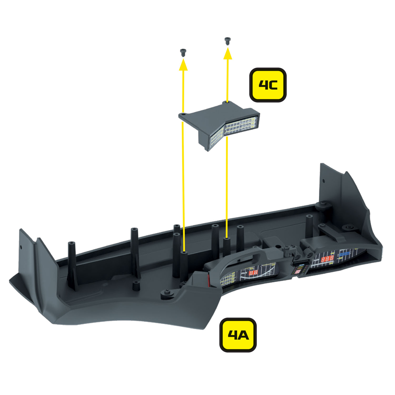
- 4C – Lower right dash housing
- 4I – Lower instrument panel
- 4D – Monitor housing
- 4J – Monitor screens
- 4P – Lower right button panel housing
These components will not be reused.
Excluding these parts, you are free to build up to Issue 42 where the Pro Speaker and Alpha Circuit Pro are installed in place of the stock speaker and mainboard. You can also skip to ‘Step 7 Preparing the Mike Lane Dashboard Monitors – Firmware upgrade’.
Part or complete builds
The Ultimate Electronic Kit is designed to be installed at Stage 42 onwards. You will need access to the underside of the dashboard, the underside of the interior floor panel, the front nose, and the front and rear outer wings.
Disassembling your model
If you have built past Stage 42, or even completed your model, you will need to disassemble your model by carefully following the original magazines and build instructions – but in reverse.
Carefully bag and tag each component that you disassemble, labelling the issue number and part numbers on each bag to make it easier to reassemble later.
You will not need to disassemble every component or assembly. You will only need to disassemble the required sections to give you the access you require to install this modification.
Step 6 Preparing the dashboard housing
Remove the following parts previously installed in Stage 04 of the build.
- 4E – Right instrument housing
- 4F – Left instrument housing
- 4G – K.I.T.T voice box
- 4H – Start-up panel bracket
- 4K – Right instrument panel
- 4L – Left instrument panel
- 4M – Front panel of K.I.T.T voice box
These components will not be reused.
If you have already installed the Mike Lane Dashboard Monitors, please remove them for the installation of the lower dash flexible circuit board and panel.
The following items need to be removed:
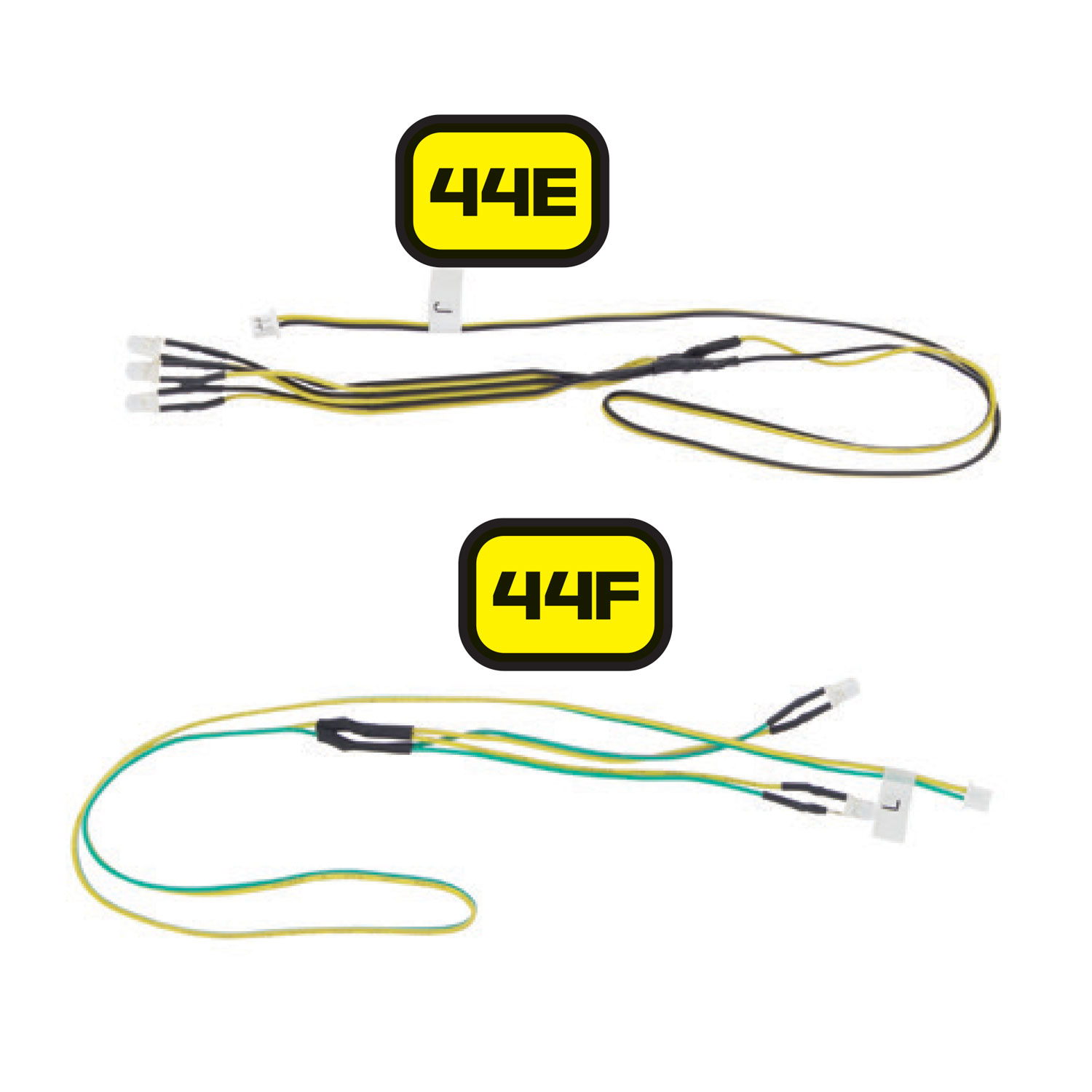
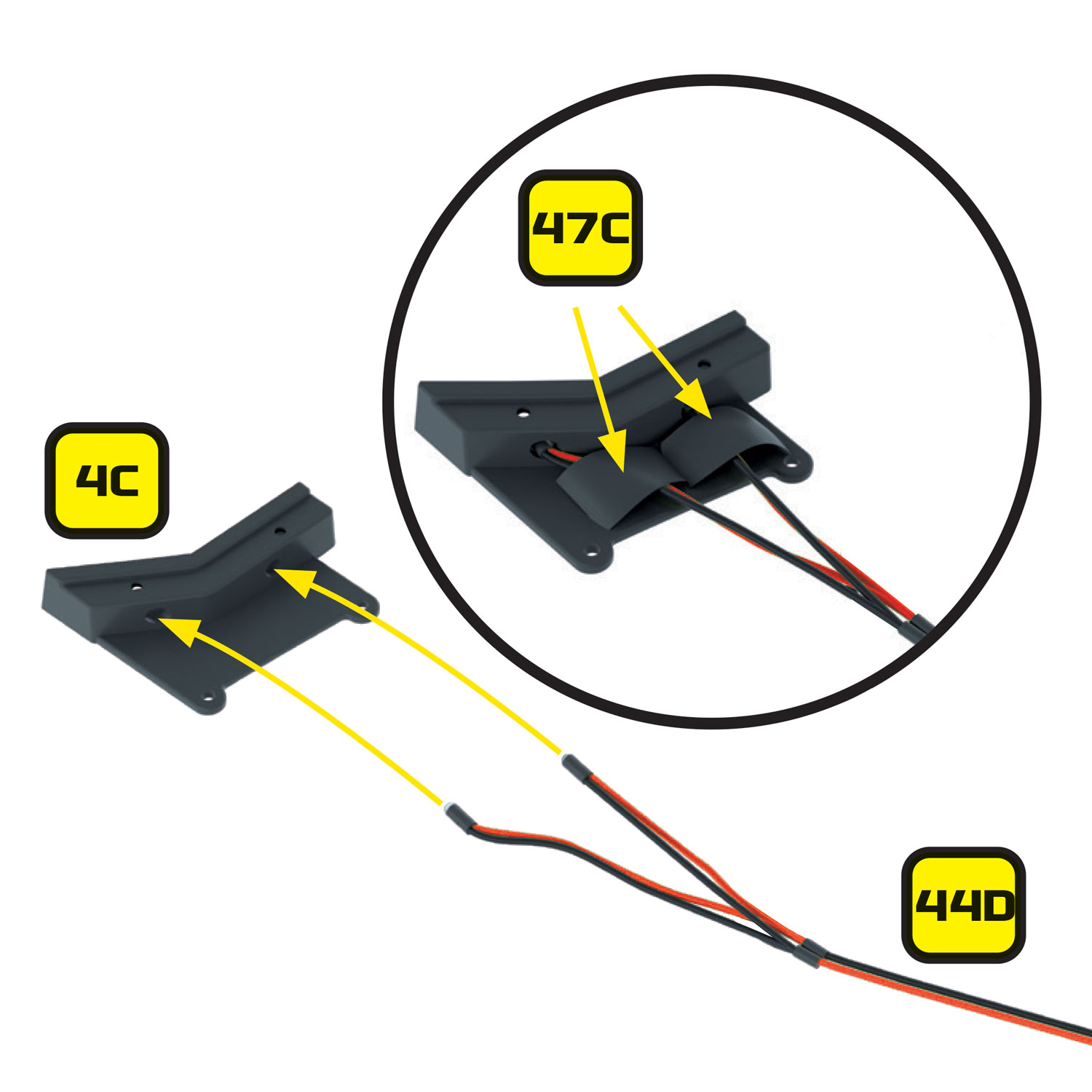
- The 3 x LED’s that feed into the lower dash – 44E (J) with the yellow cables and part 44B (G) with the red cable
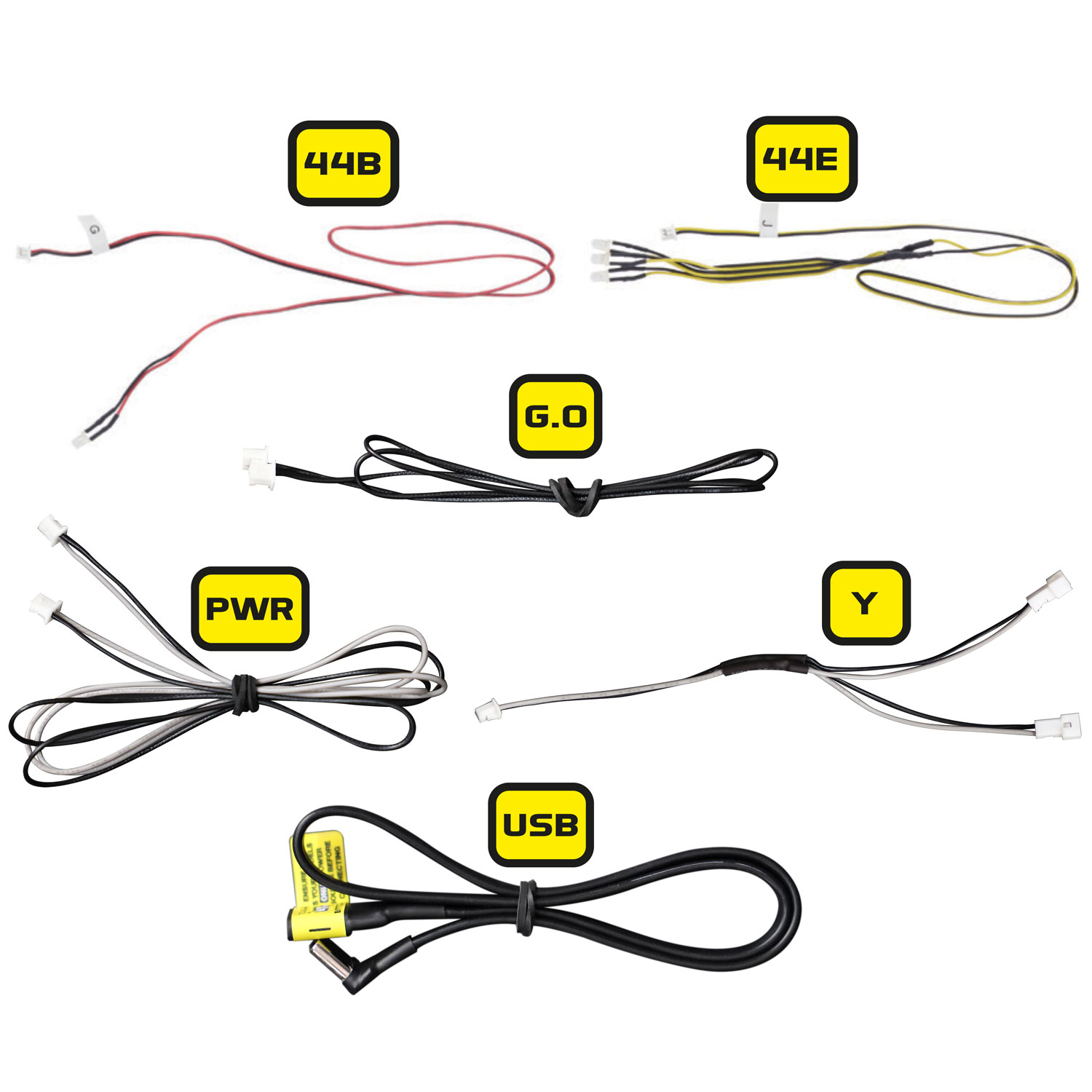
- The black G.O data cable that was supplied with the monitor kit
- The black and grey PWR power cable that was supplied with the monitor kit
- The black and grey Y-splitter cable that was supplied with the monitor kit
- The USB power extension cable that was supplied with the monitor kit
None of these cables will be required again – communication and power to the monitors will be provided through a new 5-core cable supplied within the Ultimate Electronic Kit.
Step 7 Preparing the Mike Lane Dashboard Monitors – Firmware upgrade
If you purchased your Mike Lane Dashboard Monitors separately before June 2024, then you will need to perform a firmware upgrade on them to ensure compatibility with the Alpha Circuit Pro and to make use of the exciting new capabilities.
If you purchased the Mike Lane Dashboard Monitors together with the Ultimate Electronic Kit, then you can skip this step – they will already be installed with the latest firmware and no update is required.
Any monitors purchased after this date will be fully compatible with the Alpha Circuit Pro out of the box, but may still benefit from updates in the future when newer firmware versions are released.
This is a critical step, it only takes 2 minutes and must be performed before continuing with the installation.
Firmware upgrade instructions
For detailed instructions on how to carry out an upgrade, please follow this link: https://mikelanemods.com/kitt-dashboard-monitors-firmware-update/
Step 8 Preparing for the rear side marker LEDs (Red)
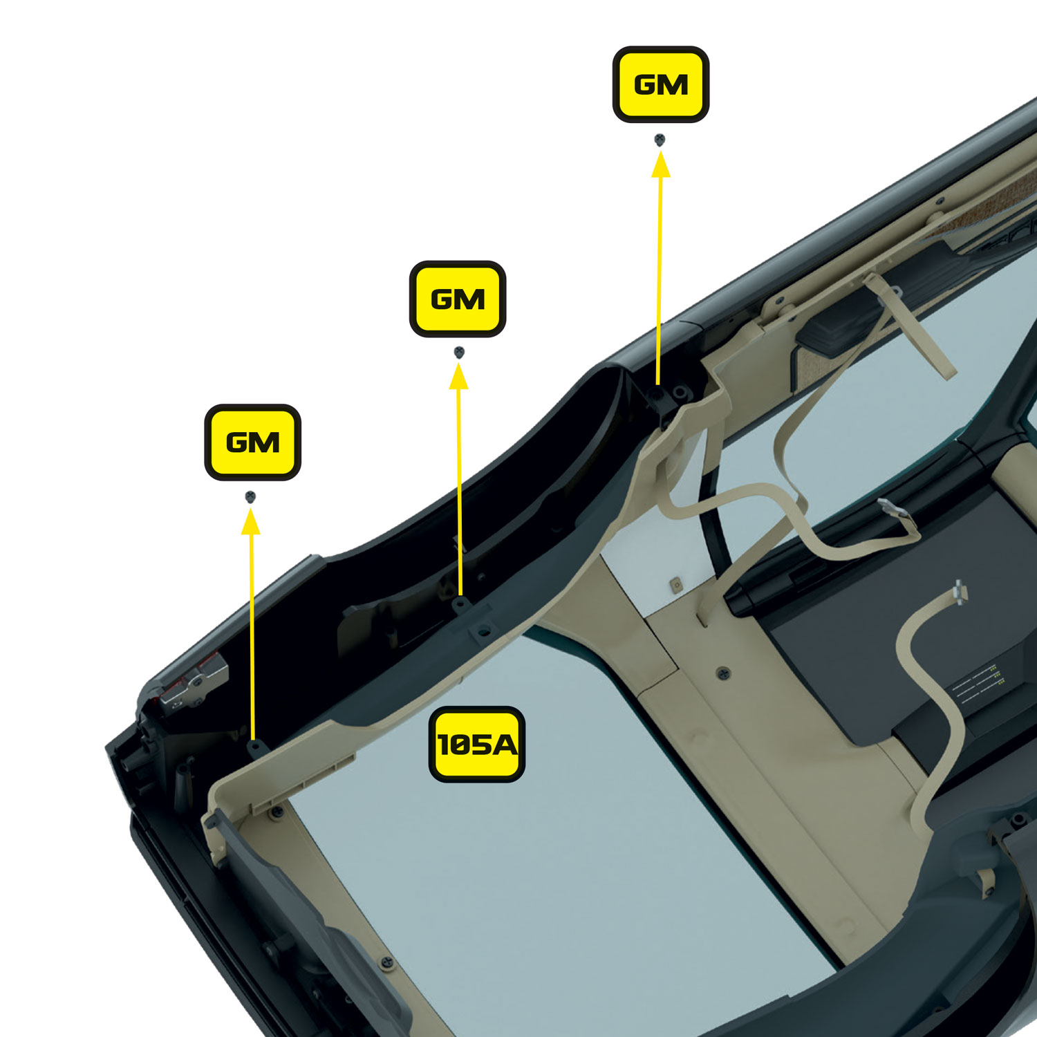
If you have already installed the rear trunk panels (102A and 105A) and the rear trunk wall (104A), you will need to remove these to gain access to the rear marker enclosures. Refer to Stages 102, 104 and 106 for details or removal and refitting.
The rear wings are now ready to take the side marker LED’s.
Step 9 Preparing for the front side marker LEDs (Orange)
Step 10 Preparing the front bumper for the new scanner
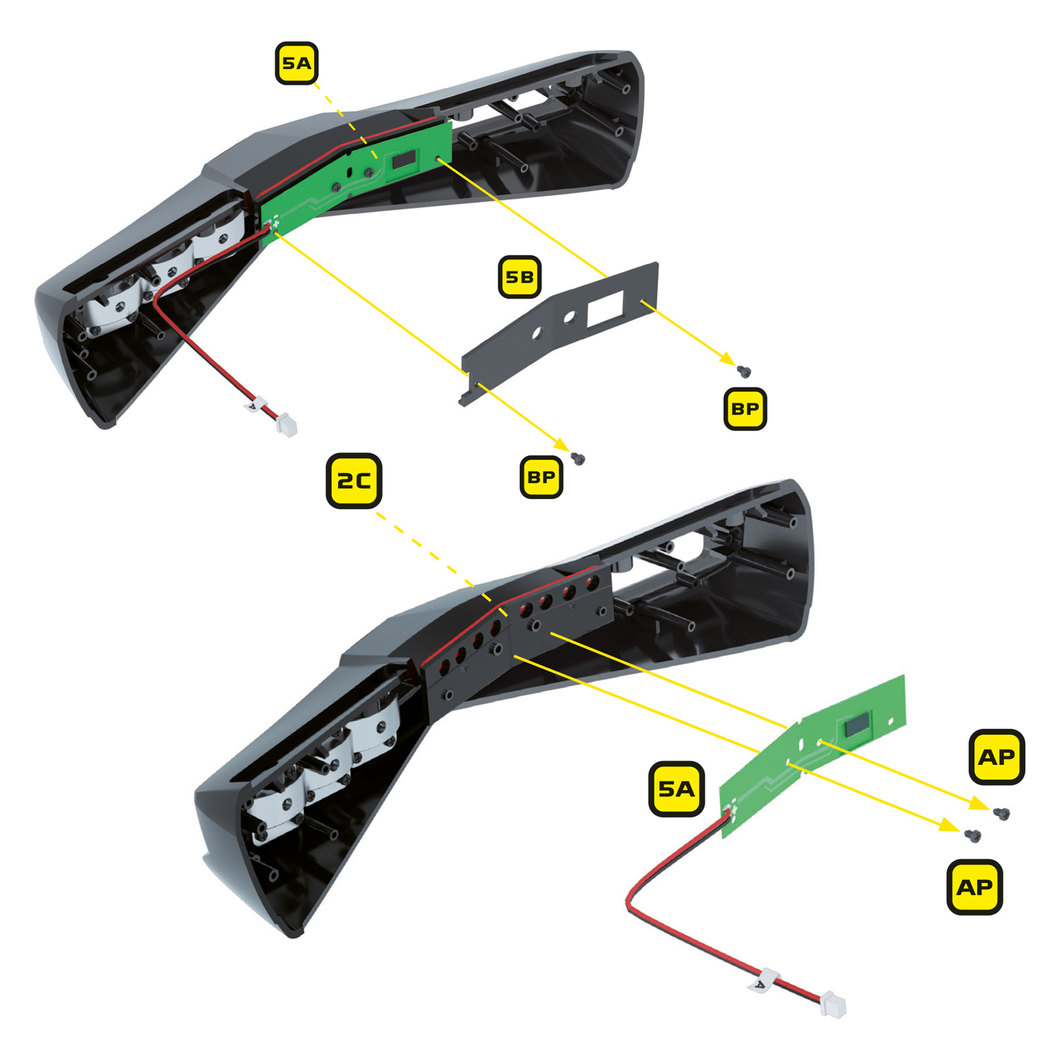
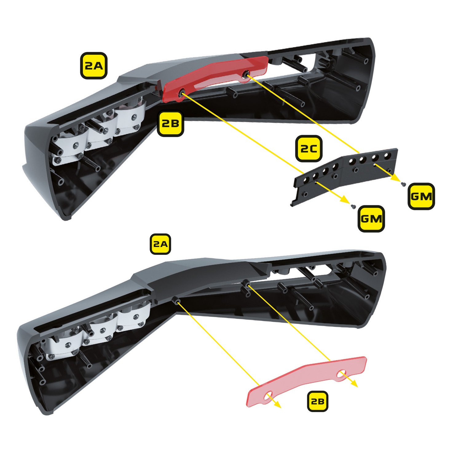
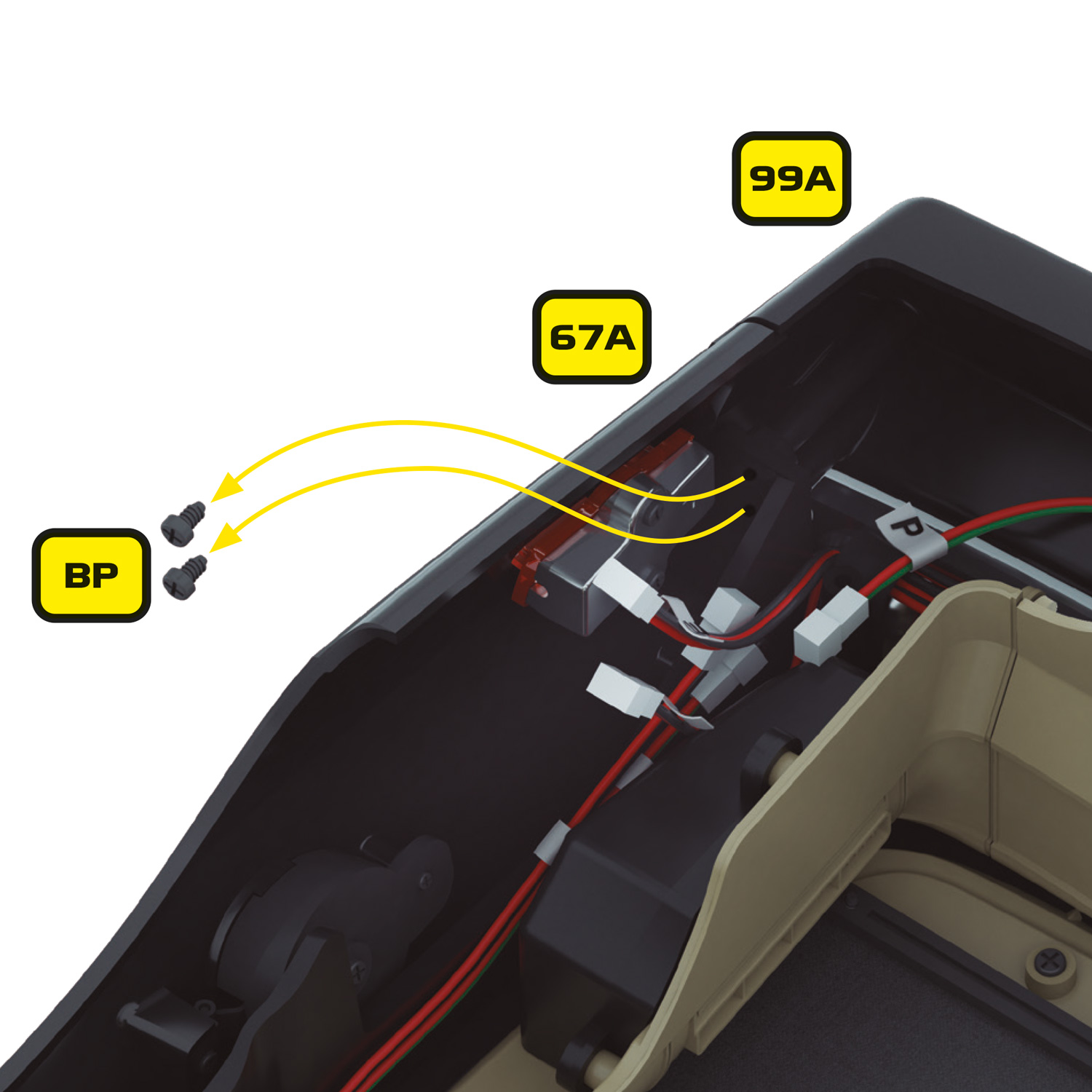
Remove the 2 x BP screws holding the inner case of the scanner (5B) in place. Next remove the stock scanner circuit board by removing the 2 x AP screws holding it in place. Except for the scanner which will no longer be needed, keep all of these parts and screws safe as they will be re-used for the Mike Lane scanner.
Step 11 Preparing the tail lights
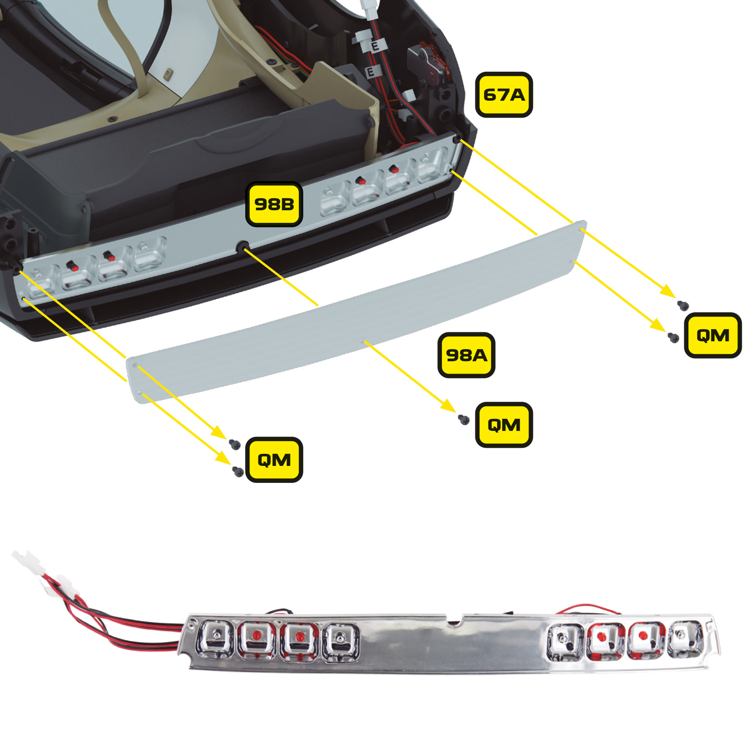
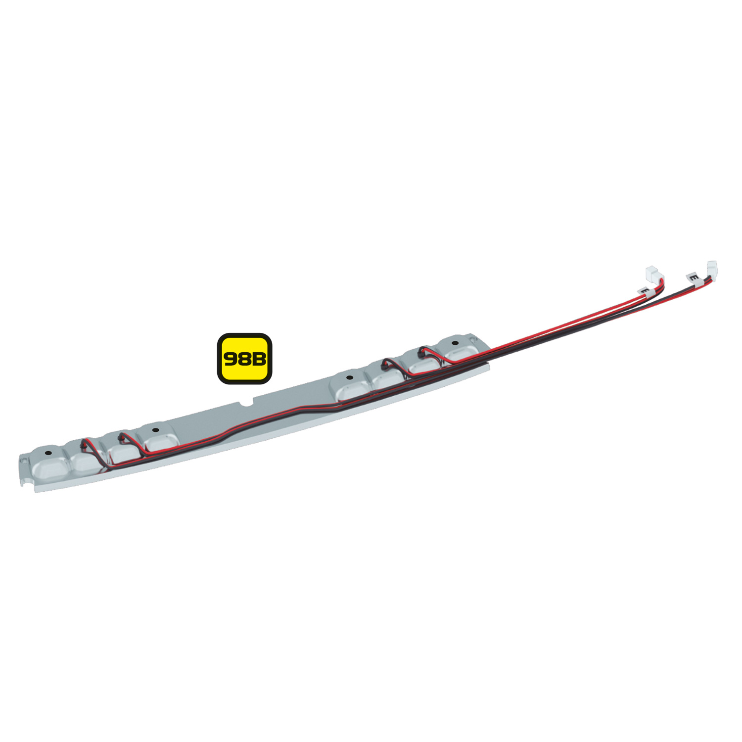
To install the additional tail lights and reversing lights, you will need to remove the tail light base installed in stage 98 and drill 4 x 3mm holes in it for the new LEDs.
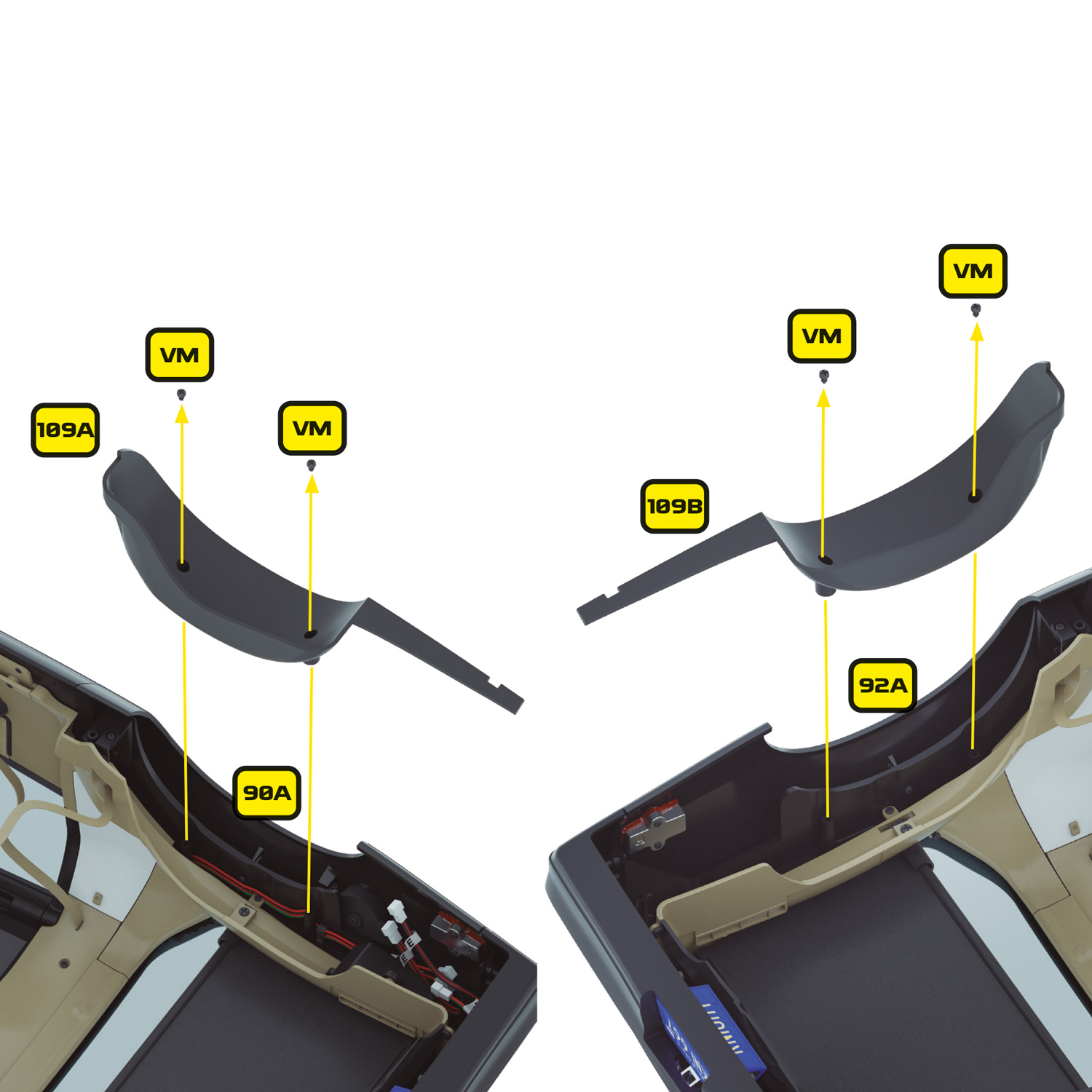
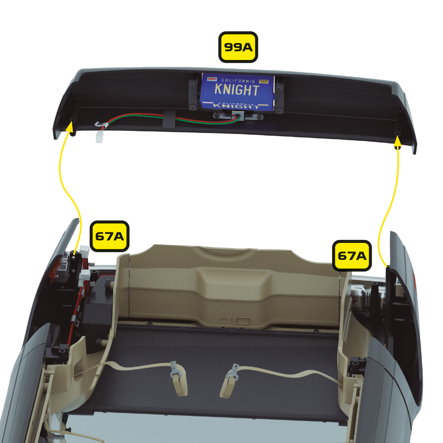
Start by removing the rear fenders (109A and 109B) installed in stage 109. These are held in place with 2 x VM screws on each fender. Keep these parts and their screws safely to one side.
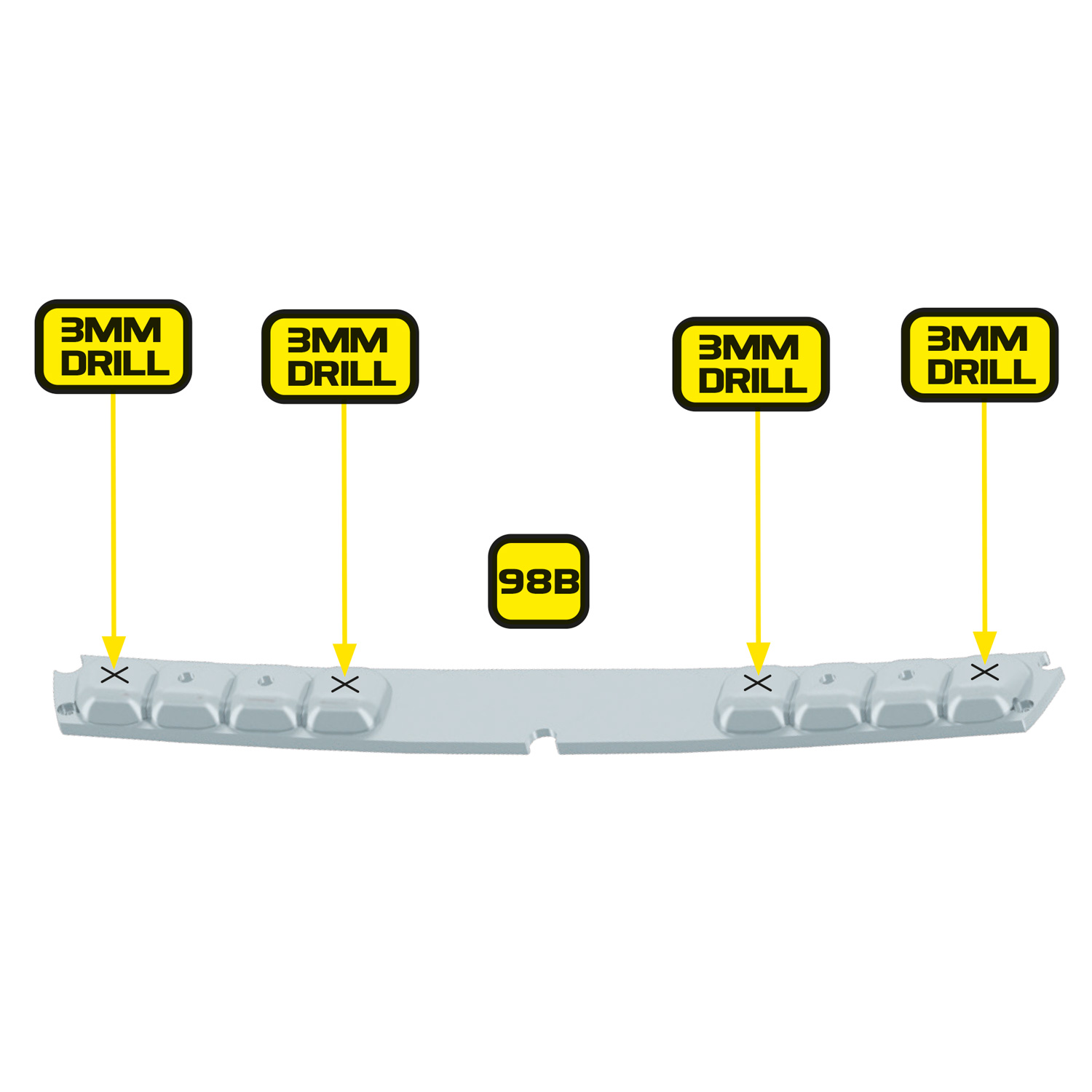
Next you will need to drill 4 new holes in the tail light base (98B), in each of the unused lamp positions. Place the base face down on a soft surface to prevent scratching and carefully mark the centre point of each lamp position. Then, using an appropriate hand drill, carefully drill a 1mm pilot hole in the centre of each lamp position, followed by a 3mm hole.
Step 1 Insert your MicroSD card (based on your board version)
First, identify which version of the Alpha Circuit Pro you have:
- If you have V1.2 – Insert the MicroSD card directly into the on‑board MicroSD slot.
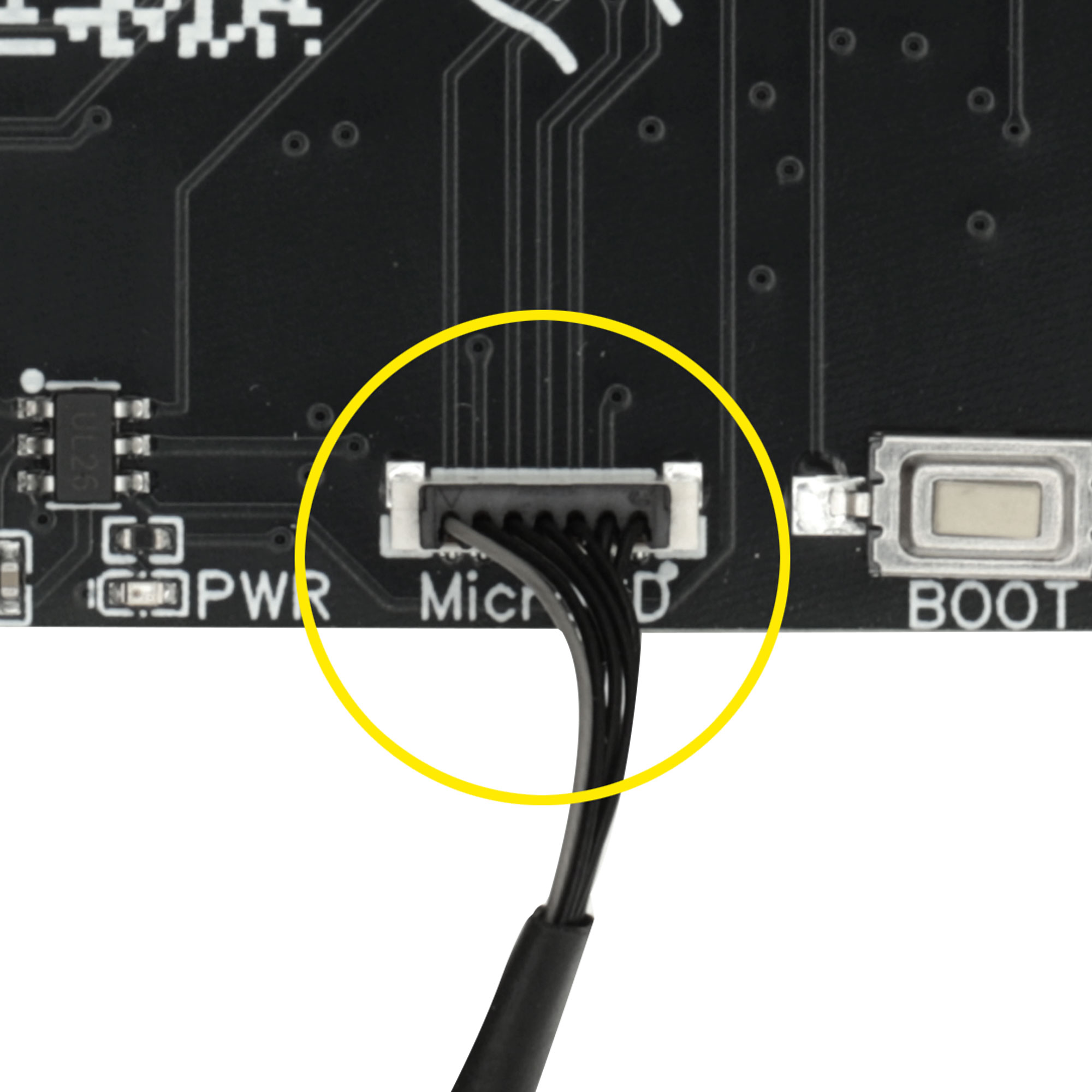
- If you have V2.0 or later – Connect the MicroSD card reader cable (Ext Cable 5) to the socket on the rear of the board exactly as shown, with the grey cable to the left, then insert your MicroSD card into the reader.
Make sure the MicroSD card is fully seated before continuing. The Alpha Circuit Pro won’t function without the MicroSD card, as it contains all the configuration settings and audio files.
Warning: Handle with care
Some connectors on the Alpha Circuit Pro are very delicate—particularly the smaller ones like the MicroSD socket. Always insert cables gently and ensure they’re the correct way up before connecting. Never force a connection, as this can easily damage the socket.
Each plug is keyed to fit only one way, but their small size makes them easy to damage if misaligned. Avoid pulling on the cables—always remove by gripping the plug itself. A magnifying glass may help with alignment.
Rough handling or incorrect insertion may result in damage to the connectors or surrounding components, so take your time and proceed carefully.
Step 2 Installing the Alpha Circuit Pro
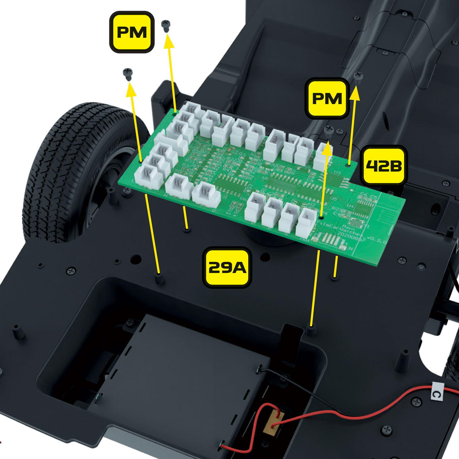
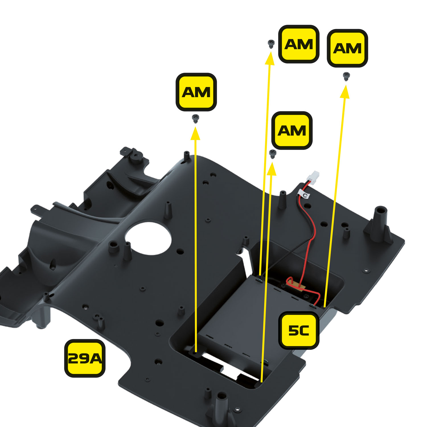
Gently place the Alpha Circuit Pro into position on the car’s chassis in the same place as the original board. The large silver component should be on the left side of the car. The board will align with the original mounting posts and should be secured in place using the original 4 x PM screws. Be careful not to over tighten the screws.
Step 3 Installing the Pro Speaker
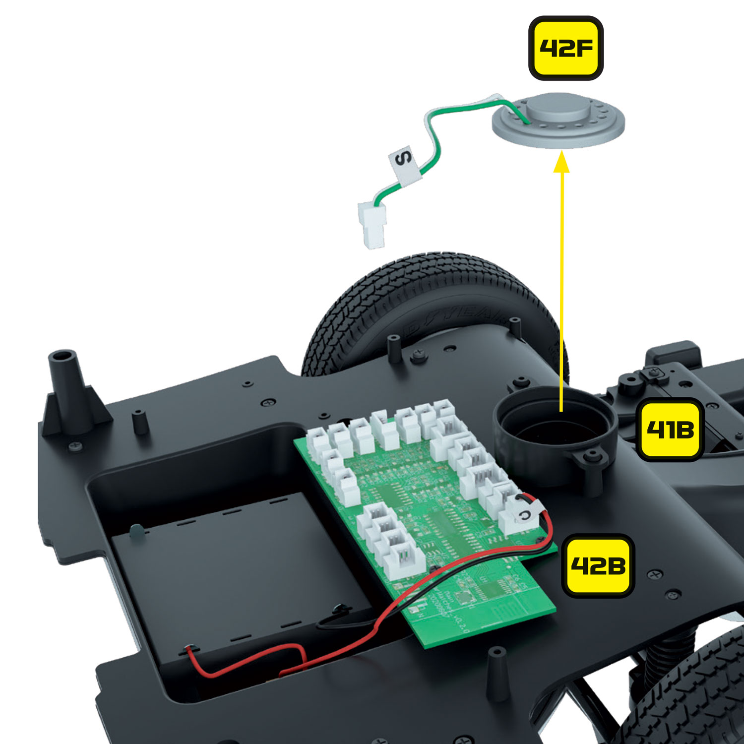
Place the replacement pro speaker facing down over the hole in the chassis. Ensure the white connector plate on the speaker is facing towards the Alpha Circuit Pro.
Connect the pro speaker cable into the socket labelled ‘S’ with the grey cable at the top as shown.
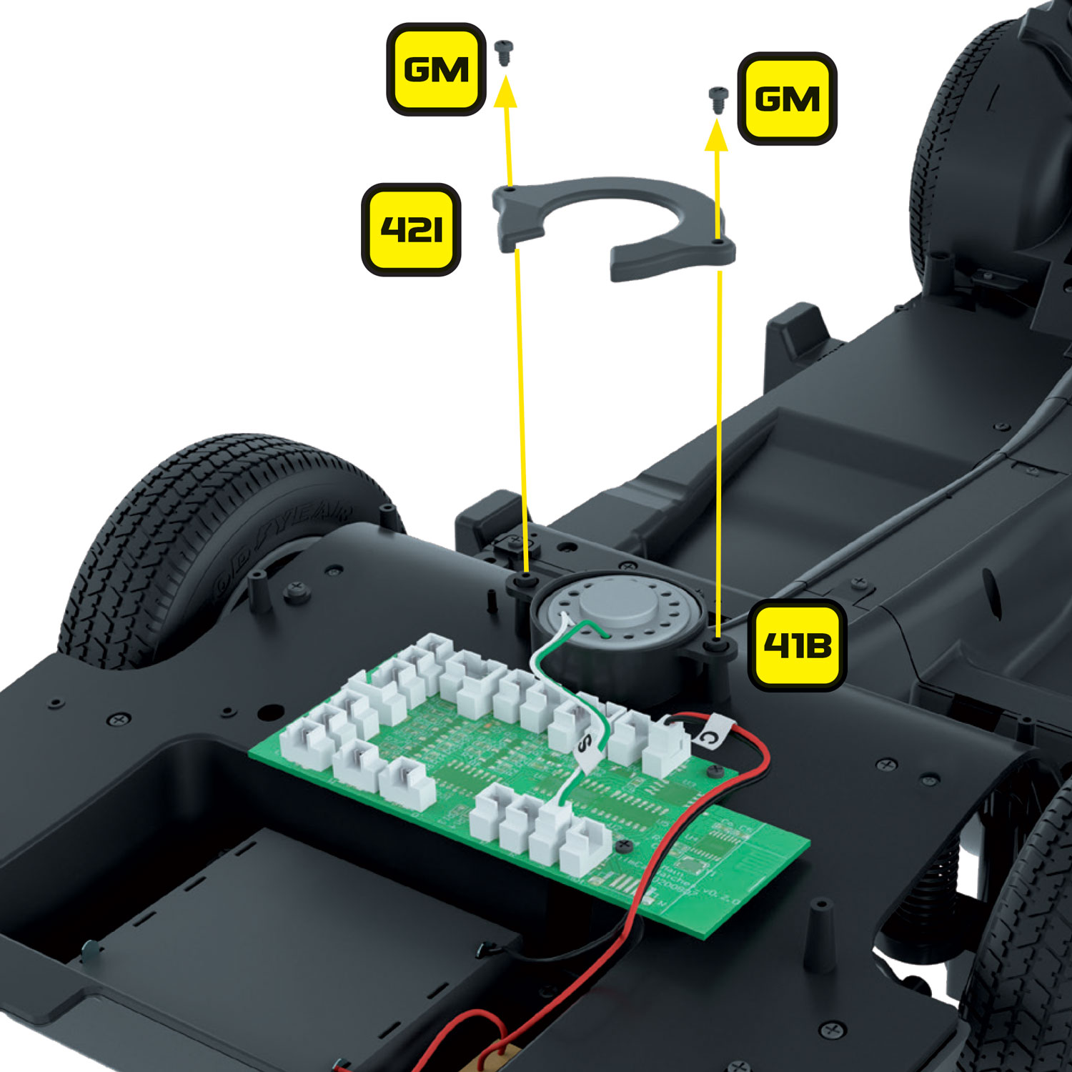
Place the speaker cover (42I) over the back of the speaker with the opening facing the front of the car (this is the reverse of the original fitting) and secure using 2 x GM screws. Due to the slightly larger dimension of the replacement speaker, the speaker cover may bend slightly at each end, this is normal. Therefore, you may not need to fully tighten the screws but ensure that the speaker is firmly held in place to avoid rattling.
Step 4 Connecting original cables to the Alpha Circuit Pro
You can now connect the following original cables to the Alpha Circuit Pro. The sockets on the Alpha Circuit Pro are labelled the same as the original main circuit board making it simple to identify which cables connect to which socket:
- 42C – Door switch wire – marked ‘B’
- 42H – Fog lights wire – marked ‘R’
- 43B – Headlights – marked ‘M’
- 43D – Popup headlight motor – marked ‘Mot’
- 43F – Overhead light wire – marked ‘K’
- 43H – Overhead light wire – marked ‘W’
- 43K – Tail lights – marked ‘E’
- 43M – Licence plate wire – marked ‘P’
Step 5 Installing the new dashboard panel with voicebox module
On the rear of the dashboard you’ll notice a small shroud behind the voicebox area. This is to isolate the voicebox LEDs (the top two LEDs as you look at the voicebox) to prevent light bleed.
Dashboard Panel 2.0
This photo shows our updated 2.0 dashboard panel. If your dashboard doesn’t look like this, please reach out and we’d be happy to organise a replacement upgraded part. Contact us here: https://mikelanemods.com/contact/
Later, when installing this into the dashboard housing, it will be important to get this sitting flush against the circuit board and surrounding the top two voicebox LEDs. If installed incorrectly it may block the voicebox LEDs.
You will get the opportunity to test this during the ‘First Electronics Test’ later in this guide. Be sure to test the voicebox area at the earliest opportunity to avoid taking too much apart if you identify an issue.
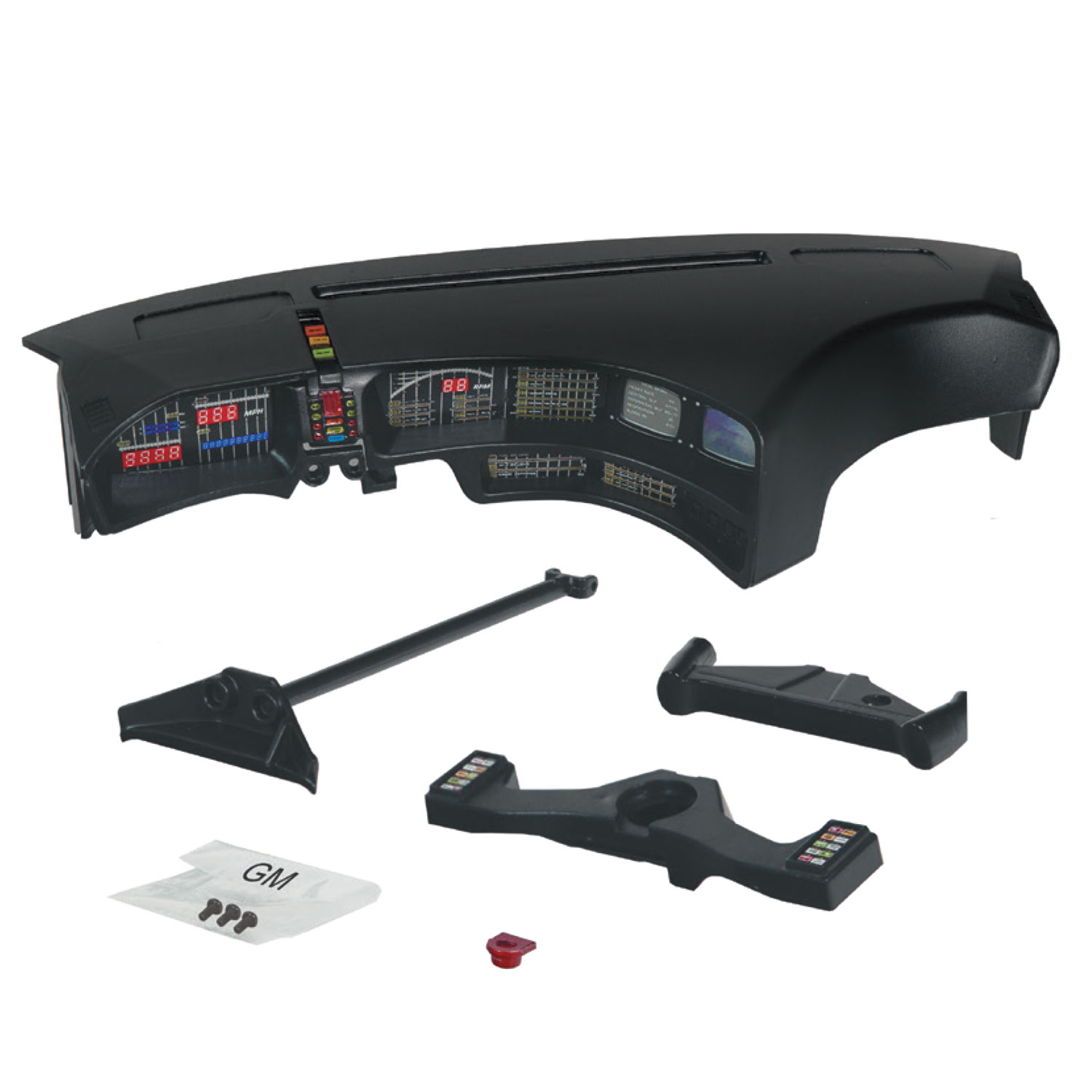
Ensuring that the left dashboard panel (4B) is removed beforehand, insert the new dashboard panel into the dashboard housing, slotting the voicebox over the allocated slot on the front of dashboard housing.
The whole dashboard panel itself will become more flush to the front of the dashboard once the circuit board is installed.
Handle the voicebox and dashboard panel with care as you install it – especially the thin area on the left-hand side of the voicebox faceplate as it risks breaking if mishandled.
This is an important step to take your time with and get positioned correctly. If when powering up you notice your KITT voicebox LED isn’t working, or is hard to see, it is most likely because the shroud has become bunched up behind the dashboard.
Step 6 Securing the electronic dashboard circuit board and installing the start-up panel
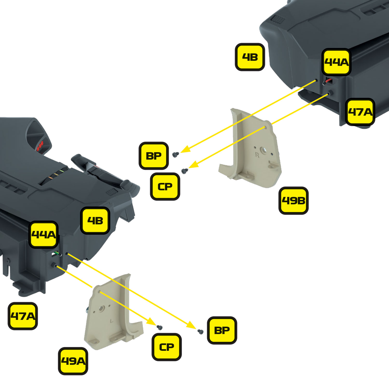
Push the left and right dashboard mounts securely onto their screw fixing points. Only push on the mounts, not the dashboard circuit board itself – there are sockets and components on the board that may break if pushed.
Fix into place using 2 x BP screws.
When pushing the dashboard into place, take care not to push on or near the sockets on the rear of the dashboard – they are very fragile and will break if not handled with care.
Handling the short cable and socket with care, place the start-up panel circuit board into position, with the corner cutout facing towards the circuit board.
Secure the circuit board into the dashboard housing using 2 x BP screws.
Now that the circuit board is securely in place, check that the dashboard panel hasn’t moved and is securely pushed down into the dashboard housing.
Step 7 Installing the flexible circuit board and lower dashboard panel to the Mike Lane Dashboard Monitors
The lower dash is a flexible circuit board – designed to be installed exclusively with the Mike Lane Dashboard Monitors. If you do not have these, you can skip this stage and the lower dash electronics will not be used – instead the stock lower dash LEDs will be used.
The lower dash flexible circuit board is not designed or suitable for installation into the stock lower dash parts.
Revision: In the photos we show the flexible circuit board pre-connected to the dashboard. However, on reflection, the flexible circuit board and lower instrument panel are much easier to install into the monitor mount before connecting to the dashboard circuitboard.
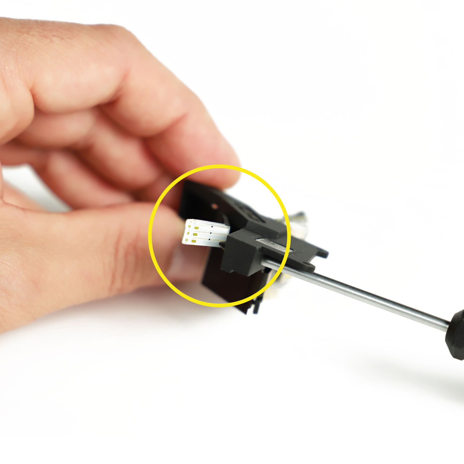
Take the Mike Lane dashboard monitors and carefully insert the flexible circuit board into its base – starting with pushing the light tunnel into the right-hand side. Once inserted, the optical tunnel should sit flush with the front of the dashboard monitors base.
Next, making sure that the flexible circuit board is inside the base, take the replacement lower instrument panel and push into place.
You should now have all the parts installed into the dashboard monitors base, with the flexible circuit board coming out of the top left portion of the lower instrument panel.
When handling the monitors, take care not to hold or put any pressure on the LCD screen. This is a fragile component and may break if not handled with care.
Step 8 Connecting the 5-core cable (cable 4) to the Mike Lane Dashboard Monitors
Connect the end of cable 4 without the label to the Mike Lane dashboard monitors socket labelled ‘CN1’ so that the grey cable is on the left as shown. The other end of the cable should read ‘TO ALPHA’ which we will later connect to the Alpha Circuit Pro mainboard.
Ensure there are no other cables connected to the Mike Lane dashboard monitors – the new 5-core cable is the only cable required.
If you ordered the Mike Lane Dashboard Monitors separately to the Ultimate Electronic Kit, you may have received the following additional cables which you will no longer need:
- The black G.O data cable that was supplied with the monitor kit
- The black and grey PWR power cable that was supplied with the monitor kit
- The black and grey Y-splitter cable that was supplied with the monitor kit
- The USB power extension cable that was supplied with the monitor kit
None of these cables will be required again – communication and power to the monitors will be provided through a new 5-core cable (cable 4) supplied within the Ultimate Electronic Kit.
Step 9 Installing the Mike Lane Dashboard Monitors back into position
The lower dash must be installed into the connector on the rear of the dashboard labelled ‘LOWER’.
To insert the lower dash circuit board into the rear of the electronic dashboard, first you must pull gently down on the dark grey retaining clip. It will move downwards approx. 2-3mm. Do not pull it completely out.
The AUX socket that you see on the dashboard beneath this socket will not be used within this installation – this is an expansion port for potential future Mike Lane upgrades.
Next, take the end of the lower dash circuit board and gently insert it into the connector with the exposed copper elements facing into the dash. While holding the circuit board in place, gently push the dark grey retaining clip back into place. The flexible lower dash should be held firmly in place and must be completely straight. If it has installed at an angle, or not fully inserted gently release the retaining clip again and start over.
Following the magazine build instructions, you can now install the following remaining parts into the dashboard to complete the assembly:
- 4T– Steering wheel – Stages 4 and 47
- 47A – Instrument panel – Stage 47
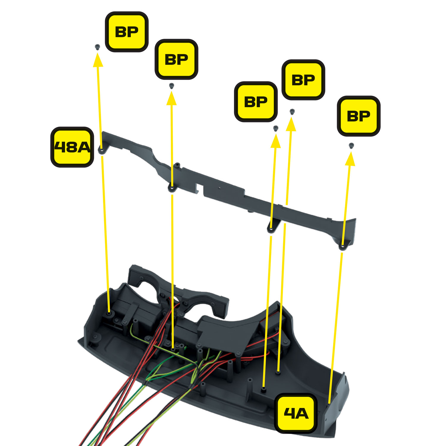
- 48A, 48B – Lower fascia panel and central console cover – Stage 48
- 4Q, 48C, 48D, 48E – Steering wheel column and bracket assembly – Stages 4 and 48
- 48F, 48G – Dashboard rear 1 and 2 – Stage 48
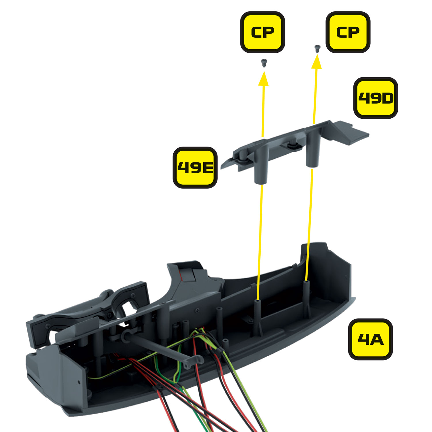
- 49D, 49E – Passenger panel 1 and 2 – Stage 49
- 49A, 49B, 49C – Interior panels – Stage 49
Your dashboard should look like the image above once these steps are complete.
Step 10 Routing the cables
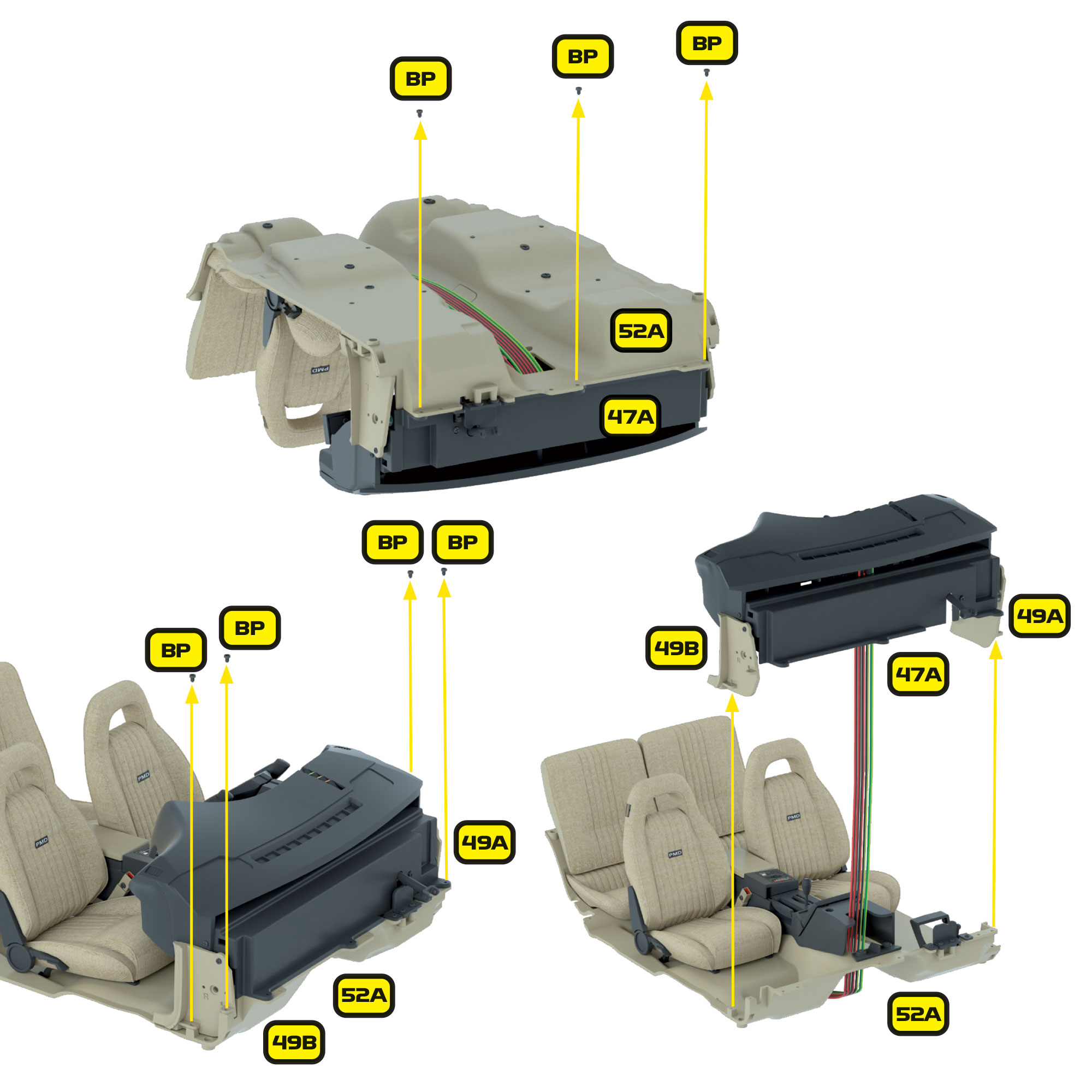
With all the dash components installed, the dashboard will need to be re-installed onto the inner floor with cables 1 and 4 routed through the hole at the front of the centre console.
- At the point you reach Stage 65 of the build, these cables should be routed to the rear of the car on the centre of the inner floor and taped down with the other original cables. Additional black strips are provided within this kit for help taping down the cables.
- The long scanner cable (cable 2) should be routed out of the side of the dash panel on the driver’s side. Please take care to ensure these cables are not damaged during the rest of the car’s assembly.
- Take extension cable 1 (ext cable 1) and route it with the existing cables along the length of the car. This cable will connect the Alpha Circuit Pro to the connector for the front side markers. It should route out of the front of the car by the driver’s side front wheel.
- Take 2 x 150mm power extension cables (ext cable 2) and connect one to the socket labelled ‘REV’ and the other to the socket labelled ‘TAIL’ on the Alpha Circuit Pro. These should be routed with the other short extension cables to the left (driver’s side) of the car for connection to the tail lights and reversing LEDs later.
- Mount the inner floor to the chassis as per the build instructions of Stage 66 taking care to carefully route the cables.
- You can now connect the following original cables to the Alpha Circuit Pro. The sockets on the Alpha Circuit Pro are labelled the same as the original board making it simple to identify which cables connect to which socket.
- 44A – Floor wire and lights – marked ‘F’
- 44G – Brake pedal wire and switch – marked ‘D’
- 44H – Steering column wire and lights – marked ‘I’
- 44I – Lower centre console wire and light – marked ‘V’
If you are not installing the Mike Lane Dashboard Monitors, then please connect:
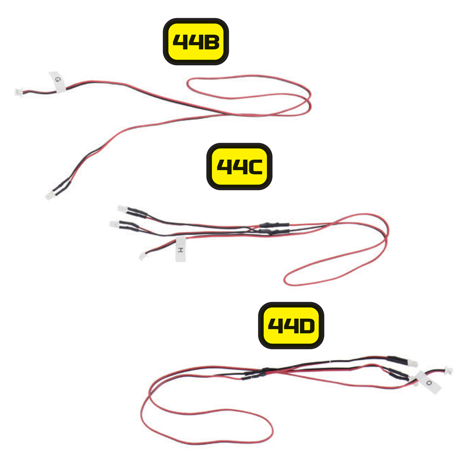
- 44B – Keypad wire and lights – marked ‘G’
- 44C – Dashboard monitor Lights – marked ‘H’
- 44D – Lower Dashboard lights – marked ‘O’ into the Alpha Circuit Pro socket labelled ‘J’
- Connect cable 1 with the end labelled ‘TO ALPHA‘ into the socket labelled ‘DASH’ on the Alpha Circuit Pro. The grey cable should be on the RIGHT when reading the word DASH the correct way up on the Alpha Circuit Pro. It should install easily and not require much force.
Warning: The connectors are very small and delicate – take care to insert them gently and the CORRECT WAY UP. The plugs are keyed to fit the sockets the right way up but due to their small size, can easily be damaged if you attempt to install upside down. A magnifying glass may be required to easily see which way up the cables must be inserted.
- At this stage we will temporarily connect the scanner before testing. Find the end of the cable 2 labelled – ‘TO SCANNER’ and connect it to the socket on the back of the scanner PCB so that the grey cable is towards the top of the board.
Step 11 Connecting your Mike Lane Dashboard Monitors to the Alpha Circuit Pro
The Alpha Circuit Pro connects to your Mike Lane Dashboard Monitors via a 5-core cable (cable 4). This cable provides power to the monitors and establishes a two-way data connection between the monitors and the Alpha Circuit Pro, so that they sync with the other electronics.
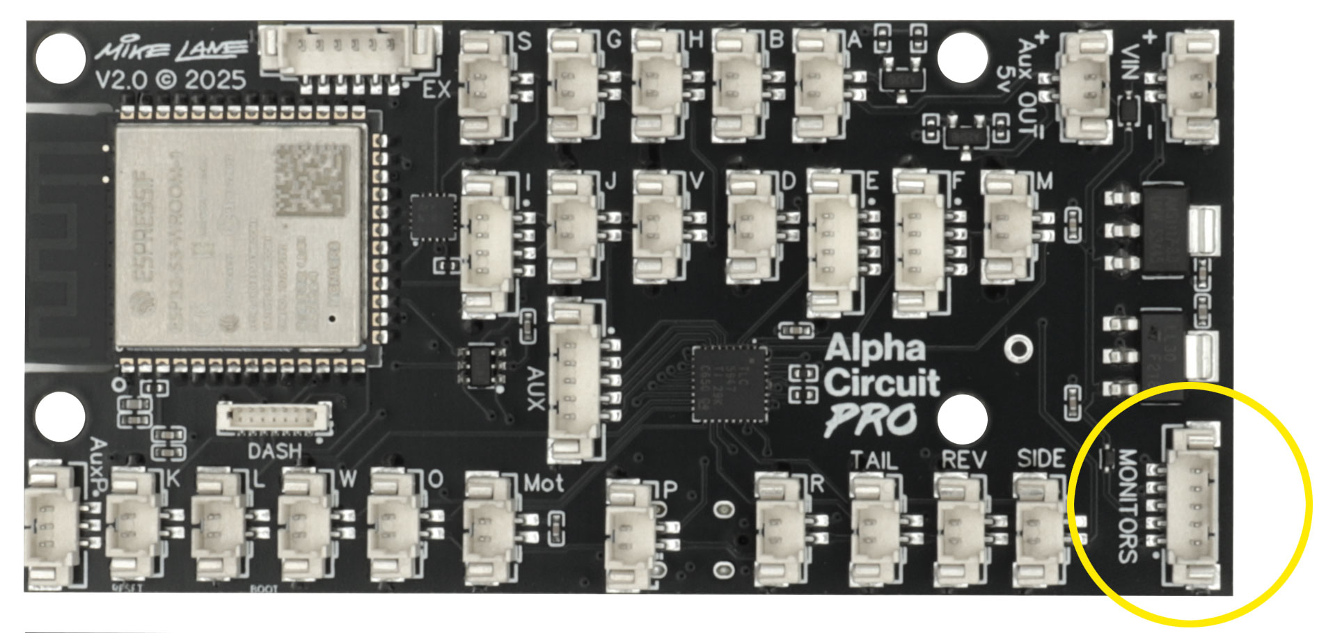
Find the end of cable 4 labelled ‘TO ALPHA’ and connect it to the socket labelled ‘MONITORS’ on the Alpha Circuit Pro so that the grey cable is on the RIGHT when reading the word MONITORS the correct way up on the Alpha Circuit Pro.
Step 12 Connecting the USB-C extension cable
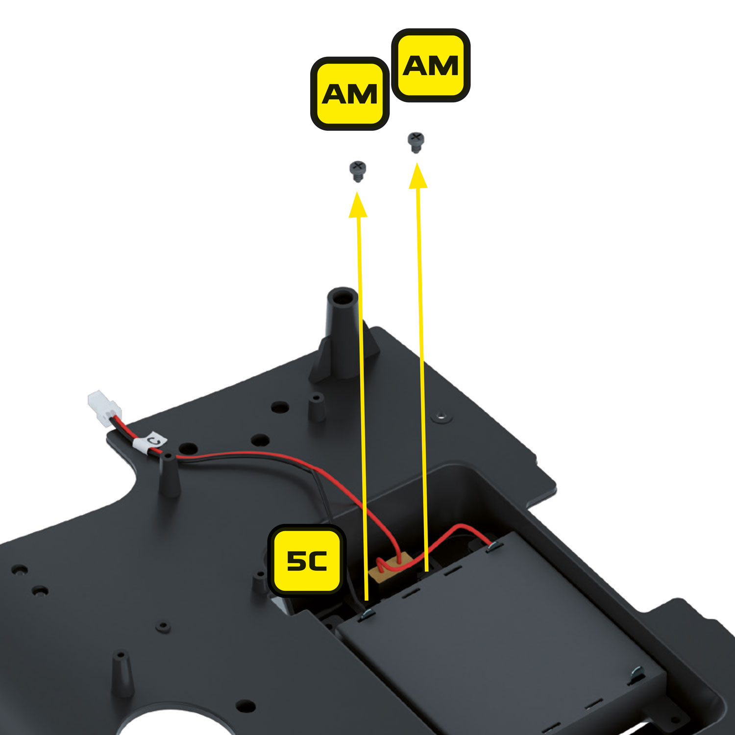
Next, feed the USB-C extender (Ext cable 5) up through the battery compartment, and plug it into the Alpha Circuit Pro.
This will hang outside of the battery compartment, on the right-hand side and is thin enough for the battery compartment lid to be refitted into place without any modifications.
This extension lead provides an easily accessible, convenient connection for the longer braided USB-C cable provided.
- Locate your new Knight Industries remote and install 2 x AAA batteries.
- Ensure everything is connected including the speaker – the first part of the setup uses voice instructions, so the speaker is important!
- Plug the braided USB-C lead (cable 5) into the USB-C extension cable (ext cable 5) on the underside of the car.
- Connect the other end of the braided USB-C lead (cable 5) to a suitable 5V 2A power adapter – as specified in the ‘Power Specifications’ section above.
- The red power LED on the underside of the Alpha Circuit Pro will illuminate and KITT will enter ‘programming mode’. This will allow you to pair your remote with KITT. Follow the voice instructions given to the very end and make sure you listen carefully to the instructions given. If you make a mistake, it will give you the option to restart at the end.
The transcript reads as follows, which you can translate on this page if not English-speaking:
KITT is now in programmer mode. Press Button 1 on your remote to start saving the button codes.
Now press Button 2
Now press Button 3
Now press Button 4
Now press Button 5
Now press Button 6
Now press Button 7
Now press Button 8
Now press Button 9
Now press Button 10
Now press Button 11
Now press Button 12
Saving codes to memory, you can test each button.
If you are happy they are correct, you can restart KITT.
If you would like to start over, press KITT’s brake pedal to start again.
- Once complete, power cycle the Alpha Circuit Pro and test each function referring to the quick reference RF remote button controls card included to understand the function of each button.
- Once complete, power cycle KITT by either removing and reconnecting power, or pressing the reset button on the underside of the Alpha Circuit Pro.
Brake pedal switch – A working brake pedal switch is required to activate KITT’s brake lights and can also be used to put the Alpha Circuit Pro into WiFi setup mode. Therefore, this is a good time to test your brake pedal switch is working and repair if required. Upon pressing KITT’s brake pedal, you should see the brake lights illuminate and his tyres will screech.
To connect KITT to your home wifi you need to be in range of your wireless router or wireless access point and your wifi must support 2.4GHz. You will need a laptop, tablet or phone to configure the wifi.
Connecting KITT to wifi allows you to stream internet radio through KITT, and also apply future firmware releases.
KITT’s wifi configuration is performed using his built-in web portal and wireless router. There are 2 ways to access KITT’s portal:
- Holding down the pedal on start-up – this will force KITT into wifi configuration mode, or
- By pressing and holding button 12 for 3 seconds – this will enable wifi configuration mode at any time when KITT is powered on
Once wifi configuration mode is enabled, KITT will broadcast a wireless network called “K2000_Setup” for 60 seconds allowing you to set-up wifi, change wifi settings or perform firmware updates. If you do not connect within the 60 second period, the network broadcast will be stopped.
If you ever wish to delete your wifi settings or change them to attach to a new wifi network, simply repeat the previous steps and put KITT into wifi configuration mode again. There are functions within this portal for deleting or changing wifi networks and for updating KITT’s firmware when new features are released.
Step 1 Installing the rear side marker LEDs (Red)
The kit includes two sets of side markers, red for the rear of the car and amber for the front. These are to be installed into the existing enclosures.
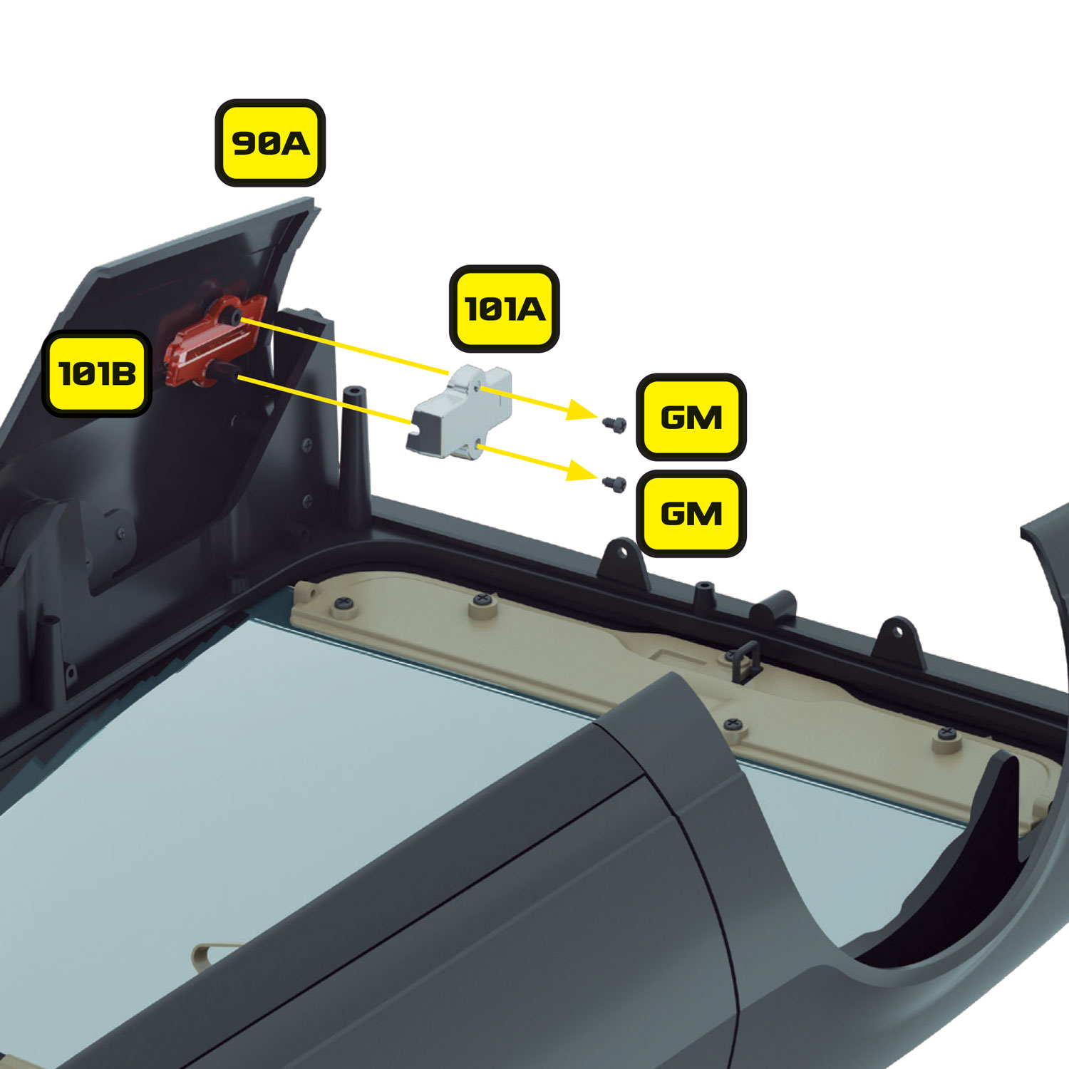
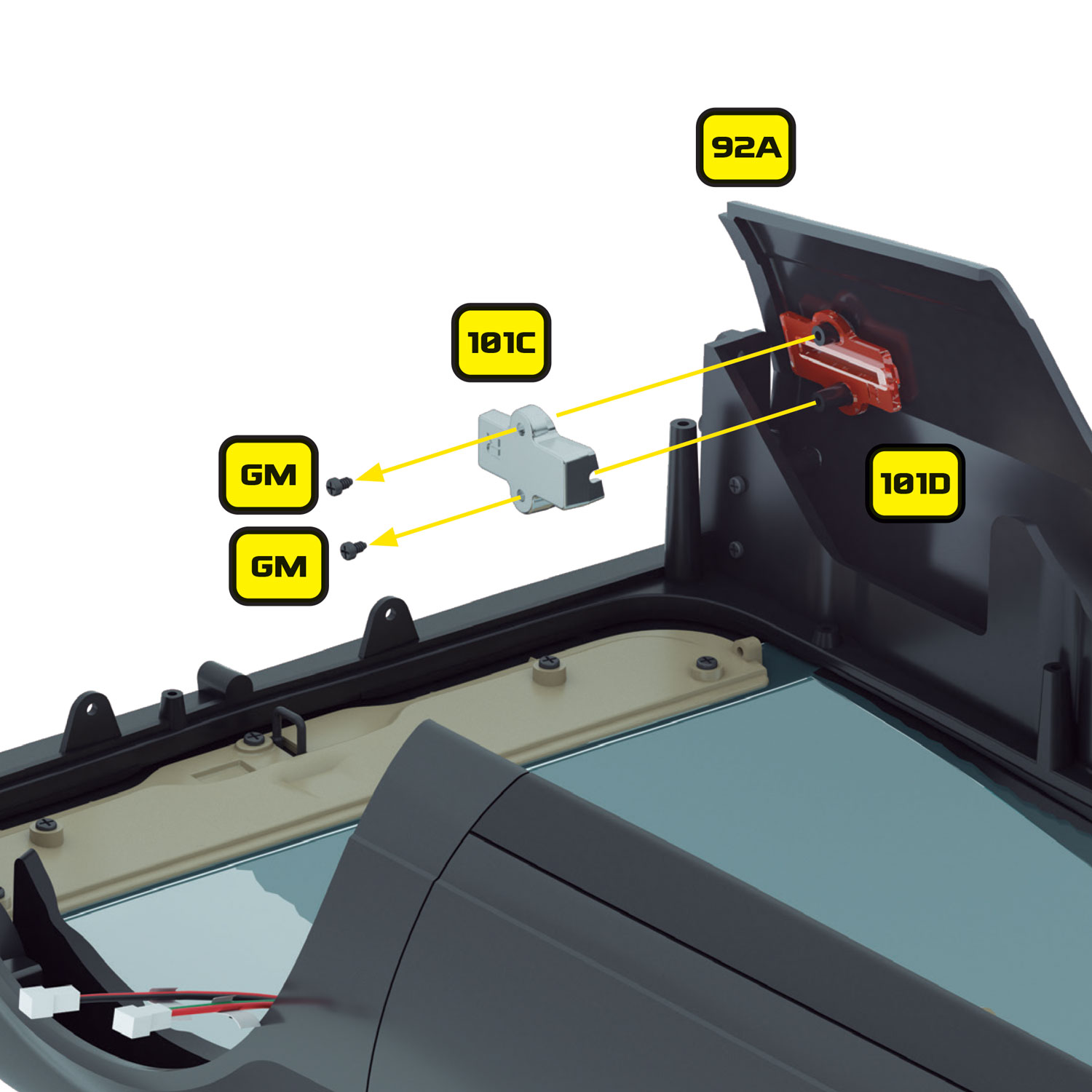
Find the red LED rear side marker lights (LED 3) from within this kit and install the LED furthest from the plug into reflector 101C. this will be re-installed on the right side of the car. The LED will fit snugly into the reflector with sufficient room for the cable to exit facing the front of the car as shown.
Carefully reattach the reflector to the car using the original GM, screws being careful to keep the LED and lens (92A) in position as you tighten the screws.
Repeat this process on the other side of the car and route the cable so that the plug is aligned with the other lighting cables near the driver side rear wheel.
Step 2 Installing the front side marker LEDs (Orange)
The front marker lenses were installed in stages 83 and 85.
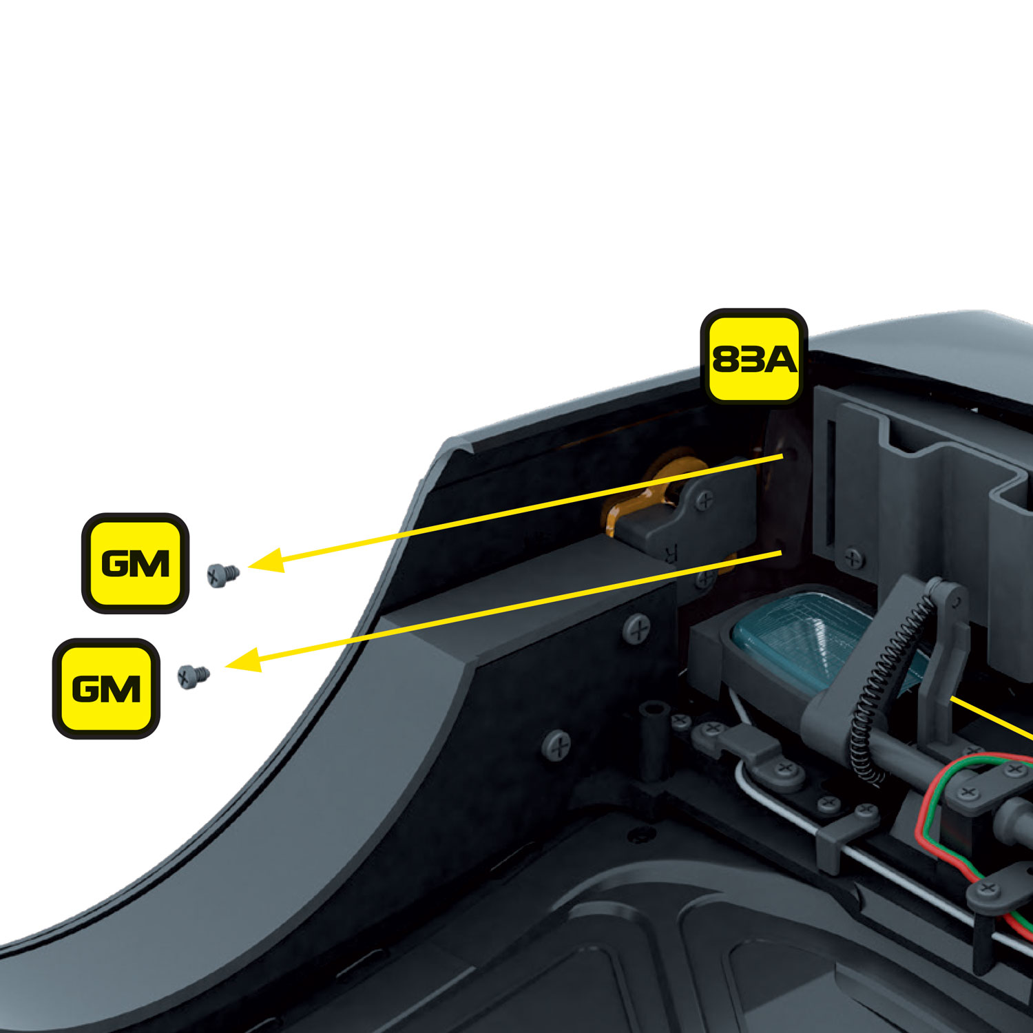
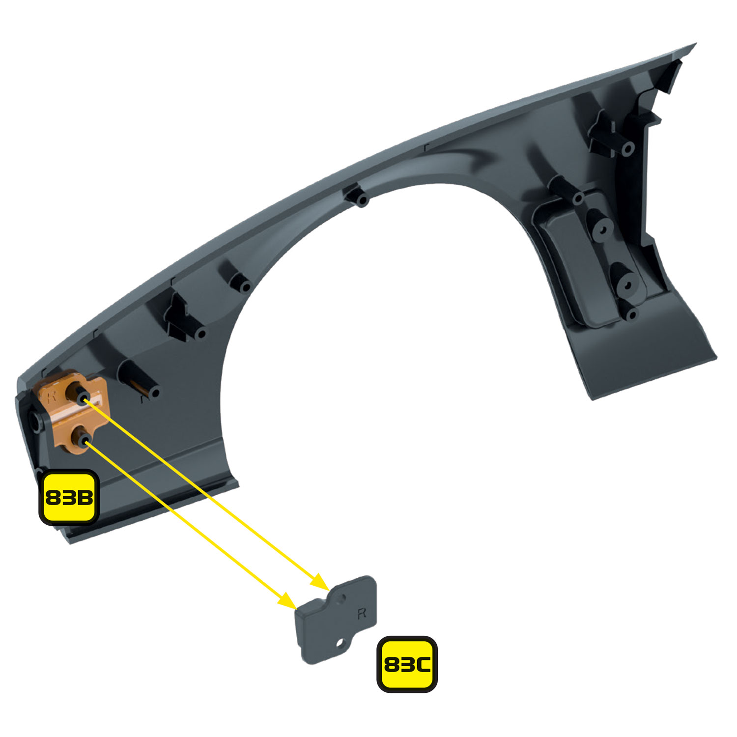
Find the amber LED front side marker lights (LED 4) from within this kit, and install the LED closest to the plug into reflector 83C. This will be re-installed on the right side of the car. The LED will fit snugly into the reflector with sufficient room for the cable to exit facing the front of the car as shown.
Route the cable for the front marker lights over the front wheel arch and through the square hole in the side of the car just in front of the door pillar.
Reinstall the front fender.
Carefully reattach the reflector to the car using the original EM screws, being careful to keep the LED and lens (83B) in position as you tighten the screws.
Now route the front marker cable across the underside of the windscreen following the existing white cable for the passenger door switch (B) where it will meet with the other cables near the front driver side wheel arch.
Repeat the LED installation process on the other side of the car and route the cable across the nose with the existing cables. The next stage requires the removal of the driver side fender so you may wish to install the led marker light in that fender during the next stage.
Now take the scanner cable (cable 2) and connect the end labelled ‘TO SCANNER‘ into the scanner socket so that the grey cable is towards the TOP.
FRAGILE CABLE: When handling the smaller cables within this kit, take care not to pull on the wires. These are fragile components and may break if not handled with care. If you need to remove the cables from their sockets, grip and pull by the plug of the cable – do not try to remove by pulling on the cable itself! A spare is included within the kit if required.
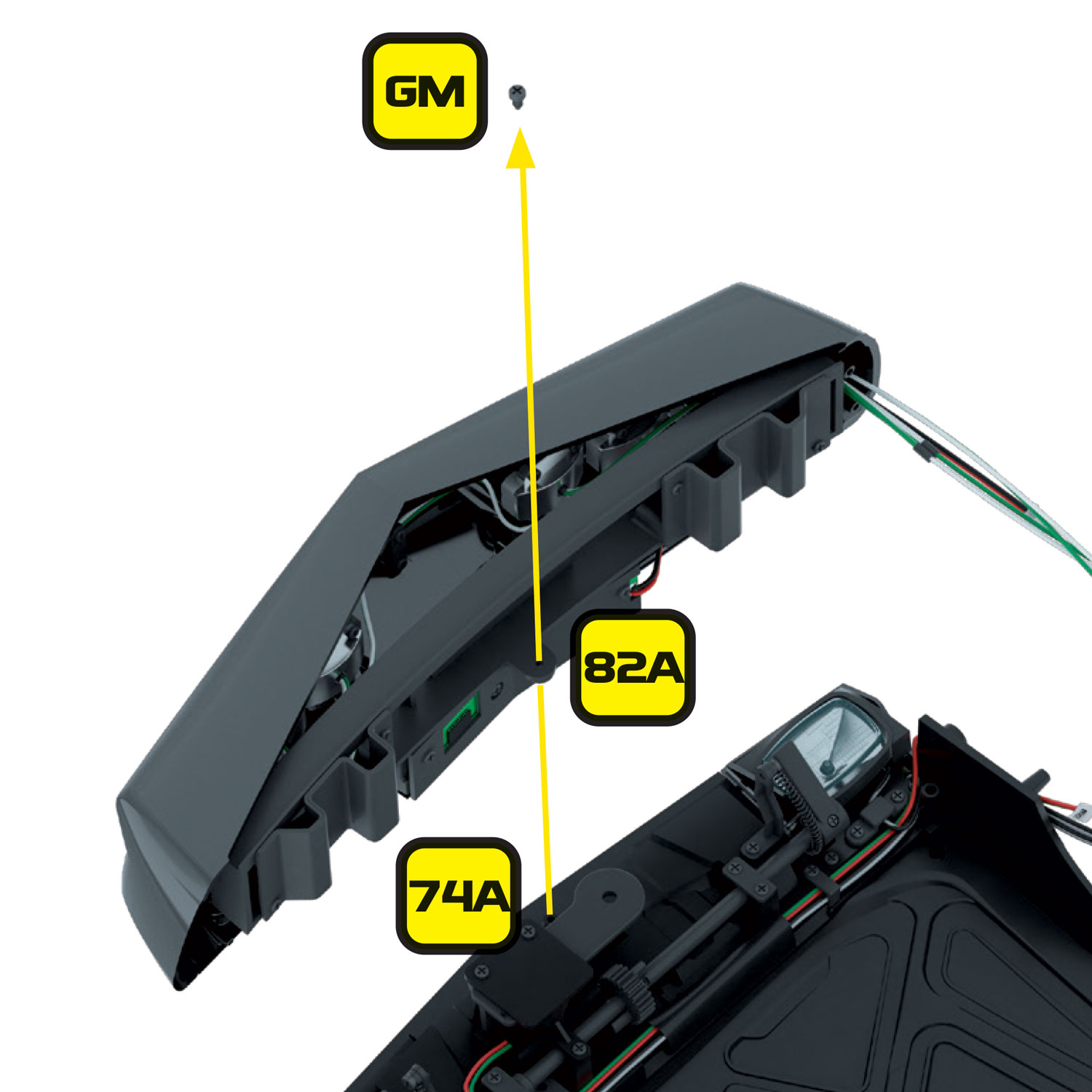
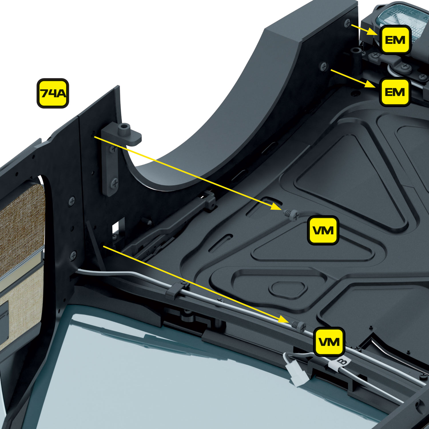
Remove the driver side fender by unscrewing the 2 x EM screws at the front and the 2 x VM screws on the rear as shown. Route the scanner cable over the wheel arch with the existing cables and route through the square hole in the side of the car just in front of the door pillar.
IMPORTANT: The scanner-to-dash cable connector should be tucked securely into the void between the engine bay and footwells. This helps prevent it from being crushed or damaged when joining the top and bottom halves of the model.
Carefully refit the driver side fender taking care not to crush any of the cables.
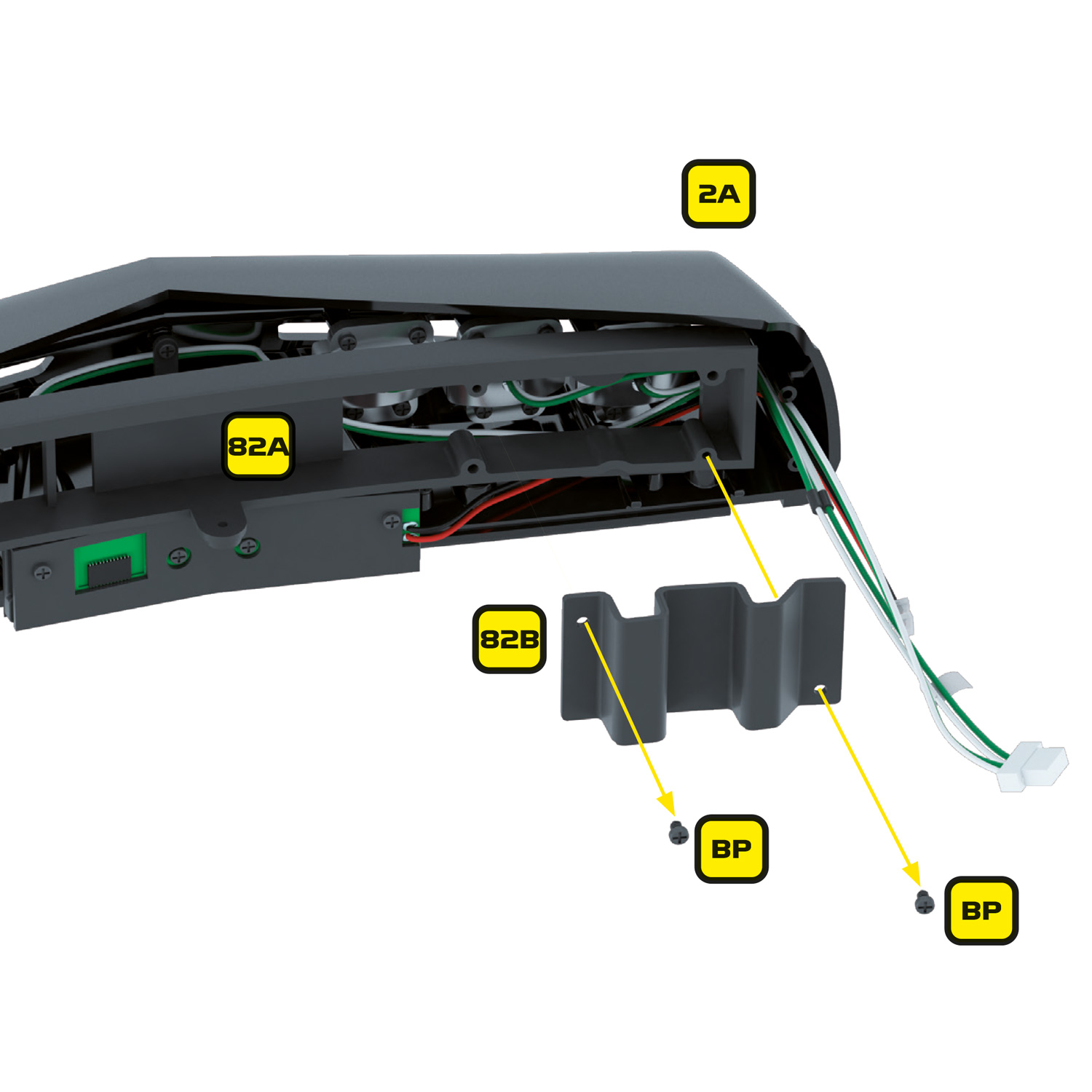
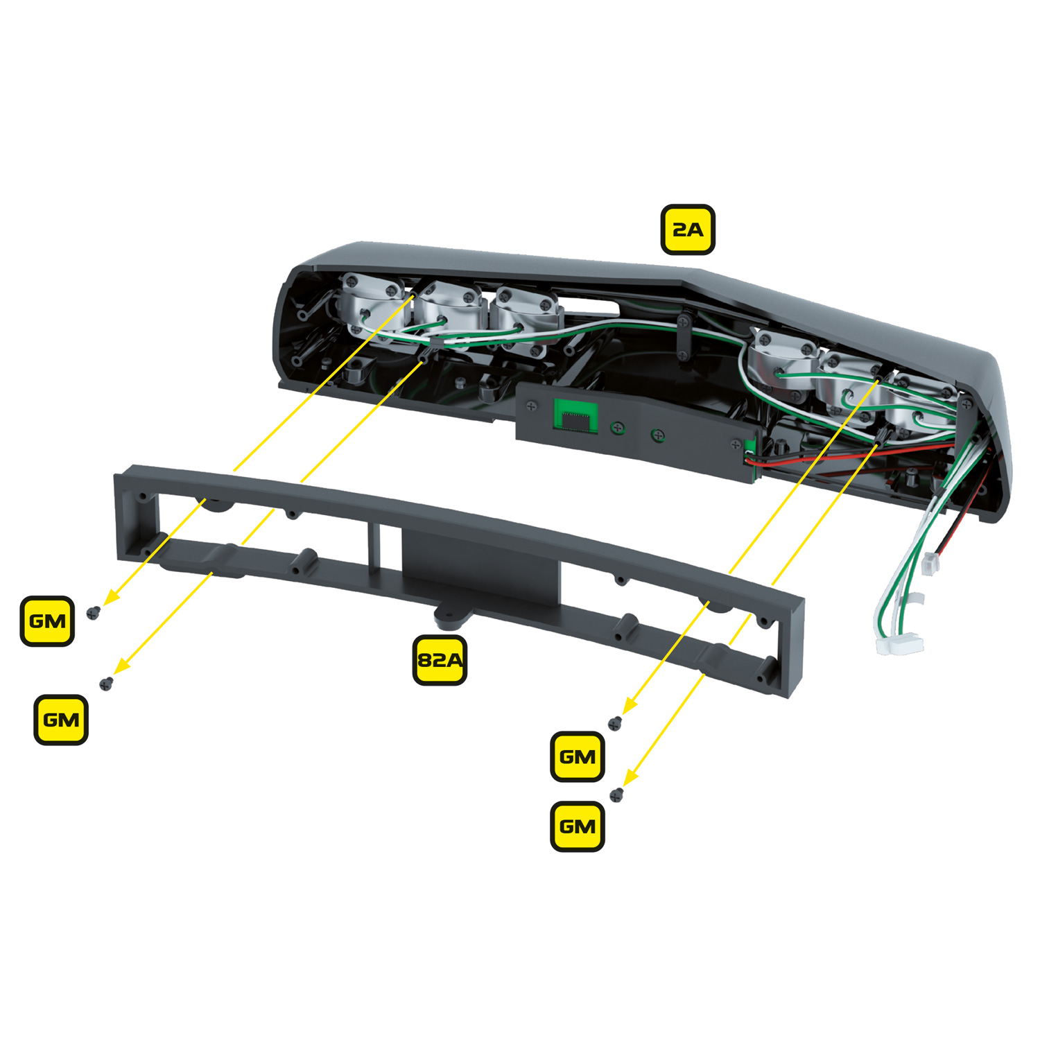
Now refit the inner frame (82A) and left and right bumper brackets (82B) and (82C) and refit the nose to the car.
Next, to use the interchangeable lenses, simply insert the bent clear lens first, then the flat coloured lens you would like to use (red for KITT or yellow for KARR) in behind the clear lens. The lenses can then be easily inserted and removed without the need to remove any screws.
After preparing the tail light base in the previous preparation steps, take the red tail light LEDs (LED 1) from within this kit and install the LED furthest from the plug into the newly drilled hole in the farthest right end of the tail light base. Once installed the LED will be on the right side (passenger side) of the car.
The remaining lamp should fit in the opposite end of the tail light base.
Now take the white reverse LEDs (LED 2) from within this kit and install the LED furthest from the plug into the newly drilled hole on the right of the tail light base as shown. The remaining lamp should fit in the remaining hole in the tail light base.
The LEDs should fit snugly but you may wish to hold them in place with some of the black tape included within this kit (trim to suit).
The plugs for the new tail lights and reversing lights should be routed to join the other cables near the driver’s side rear wheel. Connect the reversing lights to the 150mm extension cable (ext cable 2) that plugs into the Alpha Circuit Pro socket labelled ‘REV’ and connect the tail lights to the 150mm extension cable (ext cable 2) that plugs into the Alpha Circuit socket labelled ‘TAIL’.
You can now refit the tail base, tail base cover, rear bumper and fenders.
Reassemble the rest of the car as per the original instructions taking care not to pinch or stretch any of the new cables. We recommend testing the function of each electrical element at each stage of the re-assembly.
The installation is now complete!
Volume level display
When adjusting the volume, KITT’s volume level will be displayed on the scanner.
Whilst in music mode, press button 2 on the remote for Volume Up, or button 8 for Volume Down, and you will notice the scanner LEDs changing to indicate the volume level.
Pairing a replacement remote
In the event your remote control becomes lost or damaged and needs to be replaced, you will need to pair the new remote with the Alpha Circuit Pro.
To pair a new remote, you need to follow these simple steps:
- Turn off and remove power from the Alpha Circuit Pro
- Remove the MicroSD card and insert it into a suitable reader on your PC or Mac
- Delete the remotecodes.txt file located on the MicroSD card
- Reinsert the MicroSD card into the Alpha Circuit Pro and power on the device
- The Alpha circuit pro will automatically enter programming mode and will provide vocal instructions on coding the new remote
Configuration adjustments (config.txt)
Included in the kit is a MicroSD card which contains all the sound files and a configuration file used to store certain settings. This configuration file is called config.txt.
You will find the MicroSD card pre-installed into the MicroSD extender cable. You can insert the extender cable directly into a PC or Mac to access the data on the MicroSD card. Alternatively, if you need to remove the MicroSD card from the extender cable, you can slide and lift the clamshell clasp to unlock and release the card.
Here is a breakdown of all the settings that can be manually edited and what they control:
lang:EN,
Function: Language setting for KITT and KARR voice and initial remote control walkthrough.
Options: lang:EN, lang:FR, lang:DE,. Default = EN.
monitoraudio:1,
Function: Enables audio to be played that corresponds with monitor animations.
Options: monitoraudio:0, monitoraudio:1,. 1 = Enabled, 0 = Disabled. Default = 1.
shortscan:0,
Function: Disables the outer 2 LEDs on KITT’s scanner when in sweep mode. This is to replicate the scanner configuration used in the pilot episode and opening credits in earlier seasons.
Options: shortscan:0, shortscan:1,. 1 = Enabled, 0 = Disabled. Default = 0.
mute:0,
Function: Mutes the speaker. Also controllable via the remote using button 11.
Options: mute:0, mute:1,. 1 = Enabled, 0 = Disabled. Default = 0.
auxbutton:1,
Function: Determines the button associated with the auxiliary power output. See ‘Auxiliary power output’ section within these instructions for guidance on how to use this feature.
radiostation:ice-sov.musicradio.com/Heart80sMP3,
Function: Sets the internet radio station. See ‘Adjustable settings > Music settings’ for guidance on how to use this feature.
Music settings
Changing the internet radio station
If you wish to change the radio station, then please follow these steps:
- Insert the MicroSD card into a suitable reader on your PC or Mac.
- Edit the config.txt file located on the MicroSD card and change the value of radiostation: to your preferred station URL, as per the example shown below:
radiostation:ice-sov.musicradio.com/Heart80sMP3, - Save the file.
Please note
You must connect KITT to WiFi for the internet radio feature to work (See ‘Connecting to WiFi’).
Radio station URLs must be a direct URL to the audio stream and not the radio station’s website. This is usually listed as the suitable URL for Windows Media Player, VLC player or similar. However, some radio stations, particularly those who use dedicated player software or charge a subscription for listening, will not provide a suitable URL. The URL must not contain the ‘http://’ or ‘https://’ prefix. Please delete these from the URL before entering them into the config.txt file.
Adding your own music to the MicroSD Card
The MicroSD card contains a folder called ‘Music’ into which you can add your own MP3 music files. These files can be played by the inbuilt music player. Copy your music into this folder ensuring that the files are in the .mp3 format. If they contain the relevant metadata, KITT will display the track data on your Mike Lane Monitors while music is playing.
The Alpha Circuit Pro features an auxiliary 5-volt power OUTPUT for the connection of future Mike Lane or 3rd party accessories. It is labelled ‘Aux PWR’.
You can configure when the auxiliary power output is turned on by mapping it to one of the existing functions associated with the remote control within the config.txt file on the MicroSD card. By default, it is configured to be on whenever the car is powered on and not sleeping, and off when the car is sleeping.
Please note: This is a 5V OUTPUT socket. DO NOT attempt to supply any power to this socket. Use of this socket with any third-party accessories or components is done so entirely at your own risk. Ensure that the required voltage and polarity of any third-party accessories or component connected to this port matches the socket on the Alpha Circuit Pro as incorrect polarity or voltage could damage either or both devices and result in injury.
If you wish to change the button mapping for the auxiliary power socket, then please follow these steps:
- Insert the MicroSD card into a suitable reader on your PC or Mac.
- Edit the config.txt file located on the MicroSD card and change the value of ‘auxbutton’ from ‘1’ to your preferred remote button number, for example:
auxbutton:4, - Save the file.
Mapping the auxiliary power output to a specific button does not replace the button’s original function, instead it adds the operation of the auxiliary power output as shown below.
auxbutton:1, – Aux will provide power when car is on and will turn off when car sleeps
auxbutton:2, – Aux will provide power when dash is enabled and will turn off when dash is off
auxbutton:3, – Aux will provide power when car is talking after button 3 is pressed and will turn off when talking stops
auxbutton:4, – Aux will provide power when scanner is on
auxbutton:5, – Toggles Aux power on and off with button 5 (Short press)
auxbutton:6, – Aux will provide power when music is playing
auxbutton:7, – Aux will provide power when headlights or fog lights are on
auxbutton:8, – Aux will provide power when headlights, fog lights, interior lights or reverse lights are on
auxbutton:9, – Aux will provide power when the model is set to Presentation mode
auxbutton:10, – Unavailable
auxbutton:11, – Aux will provide power when audio is muted
auxbutton:12, – Unavailable
Please note
Every device is fully tested before dispatch to ensure a smooth, issue-free installation.
Most questions we receive can be resolved simply by carefully following the installation instructions step by step.
Facing issues?
If you experience any unexpected behaviour, please double-check the instructions and all cable connections carefully. If the issue persists, refer to the troubleshooting tips below.
Still need help? Don’t hesitate to get in touch—we’re here to assist you.
Alpha Circuit Pro Error & Status Codes
The Alpha Circuit Pro is equipped with various diagnostic and monitoring capabilities.
Primarily, the status is shown using various lights on the dashboard, lower console and/or upper start-up panel as shown in the table below:
A RED power LED on the upper start-up panel and lower console FLASH ON and OFF continuously
CAUSE: MicroSD card error – The MicroSD card cannot be read.
SOLUTIONS:
- Check that the MicroSD card is inserted correctly in either the Alpha Circuit Pro card slot or the extender clamshell.
- Check that the MicroSD extender is inserted properly in the Alpha Circuit Pro.
- Confirm that if using your own MicroSD card, that it was formatted on a Windows PC using FAT32.
- Ensure MicroSD card is compatible with the Alpha Circuit Pro (2TB Max) – try an alternative brand or size to test.
- Power cycle the Alpha Circuit Pro and try again once the above has been checked.
A RED power LED shows on the Alpha Circuit Pro but nothing happens
CAUSE: MicroSD may be missing or not connected correctly
SOLUTIONS:
- Check that the MicroSD card is inserted correctly in either the Alpha Circuit Pro card slot or the extender clamshell.
- Check that the MicroSD extender is inserted properly in the Alpha Circuit Pro.
- Confirm that if using your own MicroSD card, that it was formatted on a Windows PC using FAT32.
- Ensure MicroSD card is compatible with the Alpha Circuit Pro (2TB Max) – try an alternative brand or size to test.
- Power cycle the Alpha Circuit Pro and try again once the above has been checked.
A RED power LED on the upper start-up panel and lower console PULSE slowly
CAUSE: The Alpha Circuit Pro is powered on but sleeping.
SOLUTIONS:
- This is normal behaviour – use button on your remote to activate the circuit.
There is no sound
CAUSE: The audio may be muted or the speaker is disconnected.
SOLUTIONS:
- Check that your device is not muted (button 11 on the remote).
- Check that the device is not set to a volume level of 0 by using the volume up function (button 2 in music mode).
- If you’re unable to use your remote, or are unable to here the remote setup guide when binding a new remote, check in the config file that the mute setting is off: mute:0,
- Check the speaker connection.
- Replace the Pro Speaker with the stock speaker to check for any possible faults.
Remote not behaving as expected?
If some buttons don’t work, or certain modes take multiple presses to activate, there could be a few simple causes.
POSSIBLE CAUSES:
- The remote batteries may be low
- Buttons are being pressed too quickly in succession
- You’re too far from the model
- The remote may need rebinding to the power mod
- Wireless interference or obstructions near the model
SOLUTIONS:
- Replace the batteries with fresh, non-rechargeable ones – rechargeable batteries often can’t supply sufficient voltage, even when fully charged.
- Use a Test Circuit Pro (if available) to check each battery
- Move closer to your model to ensure a stronger signal
- Ensure a clear line of sight between the remote and the model — avoid obstructions or interference near the antenna
- Press buttons slightly slower when switching modes — give the system time to respond
- Rebind your remote to the power mod using the instructions in the ‘Remote Control Functions’ section – you may have accidentally skipped some buttons during the original binding process
Orange light is bleeding into the main voicebox area
CAUSE: The rear of the voicebox isn’t positioned accurately over the LED’s on the electronic dashboard.
SOLUTIONS:
- The rear of the voicebox has rectangular holes which align and fit over the LED’s on the electronic dashboard panel. When installing the electronic dashboard panel, ensure that these holes are positioned directly over the LED’s. This will reduce any light bleed into the main voicebox area.
My Mike Lane Dashboard Monitors are not coming on
CAUSE: The monitors are most likely running old firmware or not connected properly.
SOLUTIONS:
- Ensure your dashboard monitors have been upgraded to the latest firmware. See ‘Firmware updater’ here: https://mikelanemods.com/kitt-dashboard-monitors-firmware-update/.
- Confirm that the monitors are correctly connected to the 5 core cable that comes from the Alpha Circuit Pro and that no other cables are connected to the monitors.
The KARR Voicebox LED lights up brightly but the KITT one doesn’t
CAUSE: The dashboard panel hasn’t been installed correctly and the shroud behind the voicebox is covering the KITT LED.
SOLUTIONS:
- Ensure that when you place the dashboard circuit board behind the dashboard panel that you don’t slide it down into position. You risk bunching up the voicebox shroud and blocking the KITT LED. Instead, place the circuit board into position and bring forward in behind the dashboard panel so that the shroud surrounds the voicebox LEDs and doesn’t bunch up.

