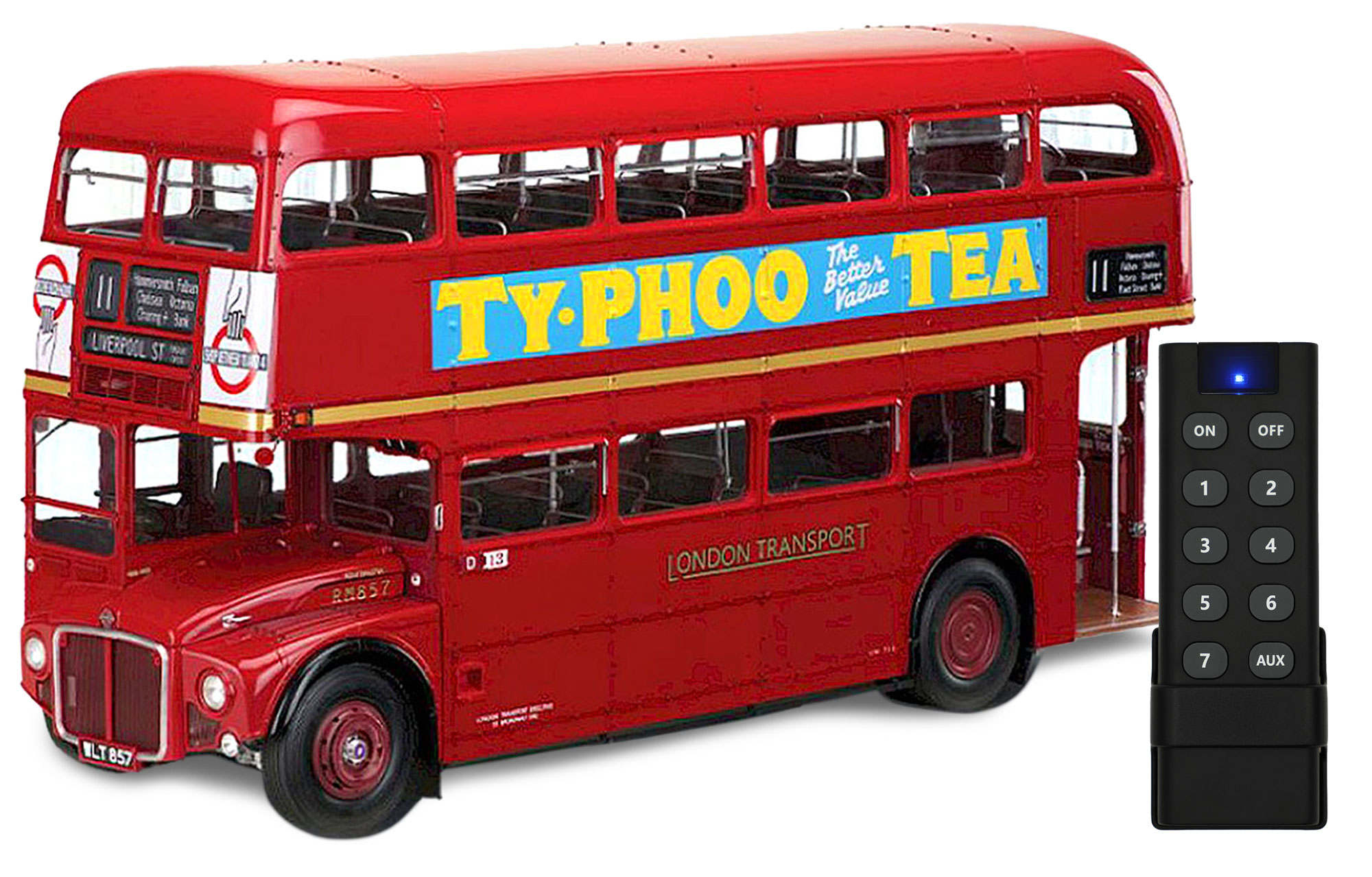
Designed for the Build the 1961 RM 857 Routemaster Bus by Agora/Hachette/IXO.
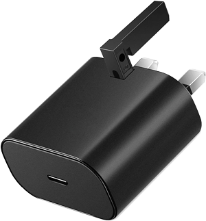
- Connect the USB-C cable to the Mike Lane Remote Control circuit board and plug in to a power source, such as a power bank, laptop, or USB-C adaptor.
- The blue LED on the Mike Lane Remote Control circuit board will light up dimly and extinguish after 10 seconds.
- Single press the programming button on the Mike Lane Remote Control circuit board.
- The blue led on the circuit board will flash to indicate that the board is ready to receive remote codes.
- Now press the buttons numbered 1-7 on the remote in this exact sequence, waiting one second between each press.
- Then press the AUX, ON and OFF buttons in that order.
During this process the LED on the circuit board will light statically and blink each time a button is pressed to confirm receipt of the button code.
When you have coded all buttons, the blue led on the Mike Lane Remote Control circuit board will flash several times to confirm programming is complete.
Bind the buttons in this sequence:
- Button 1
- Button 2
- Button 3
- Button 4
- Button 5
- Button 6
- Button 7
- AUX
- ON
- OFF
Syncing the power mod to the stock mainboard
Important: If binding a remote after power and connections to the stock mainboard have already been made, it’s important to power cycle the power mod by disconnecting power, leaving for 20 seconds and then reconnecting power. This ensures the power mod is correctly synchronised with the stock mainboard.
The buttons on the remote will now operate as follows:
| Button | Function |
| ON | Turns all lighting circuits on |
| OFF | Turns all lighting circuits off |
| 1 | Cycles Exterior and interior cabin lighting and Destination Boards |
| 2 | Driver’s cab light |
| 3 | Brake Lights |
| 4 | Sound Horn or Klaxon |
| 5 | Play engine sound |
| 6 | Play bell sound |
| 7 | Plays action sequence |
| AUX | Toggles Aux power circuit on / off |
If you make a mistake during the coding or need to code a new remote, simply restart the process by disconnecting and reconnecting the USB power from the Mike Lane Remote Control circuit board, and pressing the programming button again.
Recovery mode
If you happen to lose or damage your remote in the future, once your build is complete and when the bind button is inaccessible, don’t panic!
A recovery mode has been specifically designed in to each RF circuit board allowing you to bind a new remote using a master remote, without needing to press the bind button.
If you find yourself needing a master recovery remote please contact us, they will be available to purchase separately.
You can install this mod at any time, even when the model is complete.
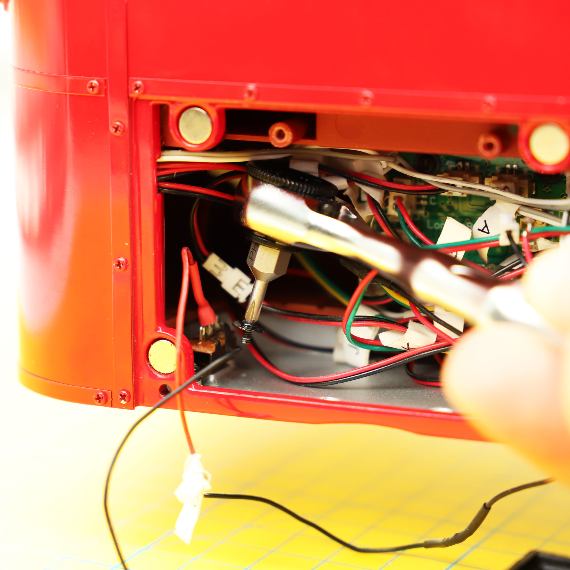
If your model is complete, you will need a mini ratchet with a PH0 bit to access and remove the battery box switch.
You can buy these here if required, we have them in stock for next day delivery in most cases. These are a great investment and super useful for all partwork model builds.
If your model isn’t complete, you can install at the point when the battery box is first fitted (issue 56).
The stock PCB is supplied at issue 57 and the custom JST-to-USB-C cable provided within this kit will route out of the small hole allocated for the battery box power switch.
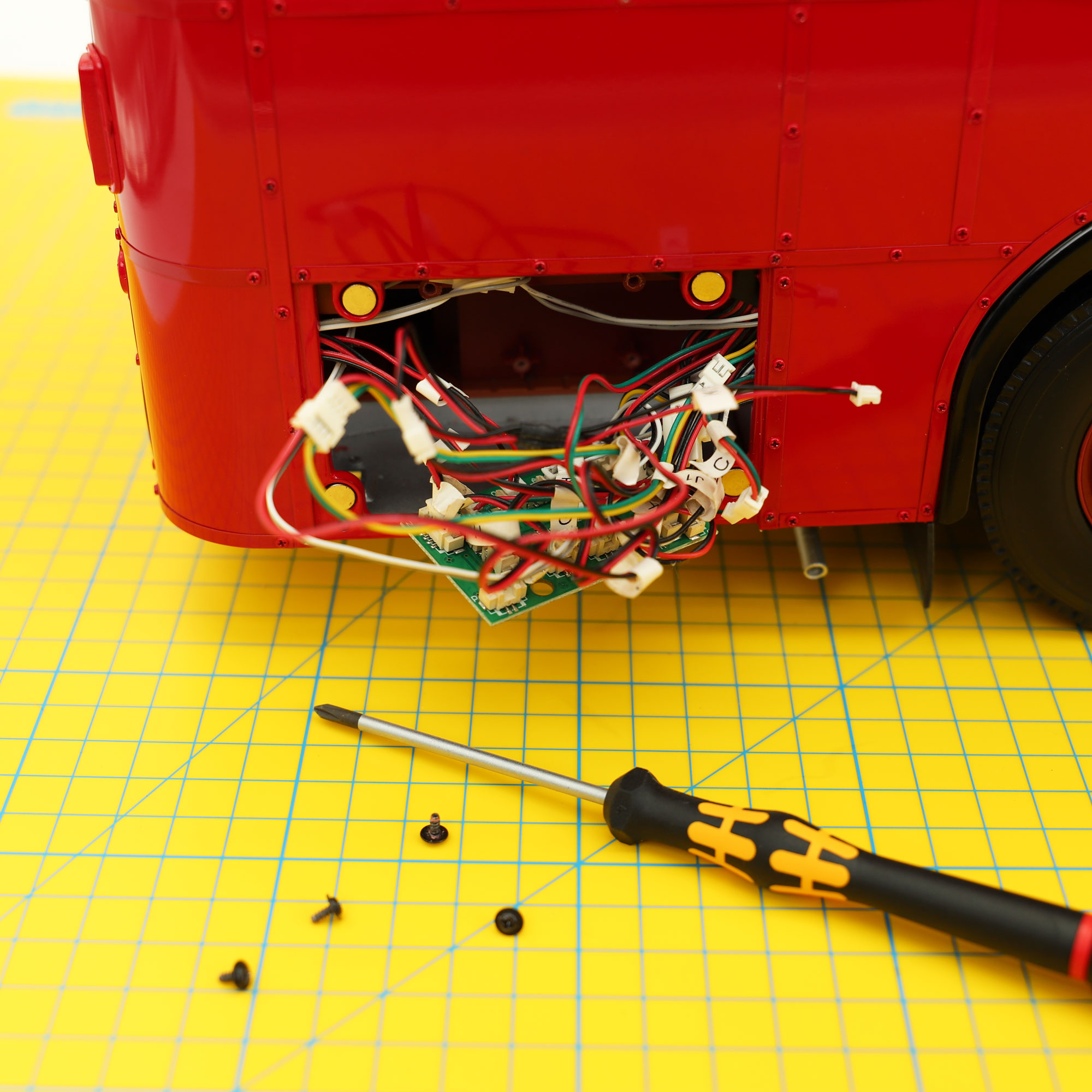
- If your model is complete, remove the magnetic battery cover, then, using a PH0 screwdriver, remove the 4 x JP screws holding the battery box in place. There are two underneath the model and two inside the battery box housing.
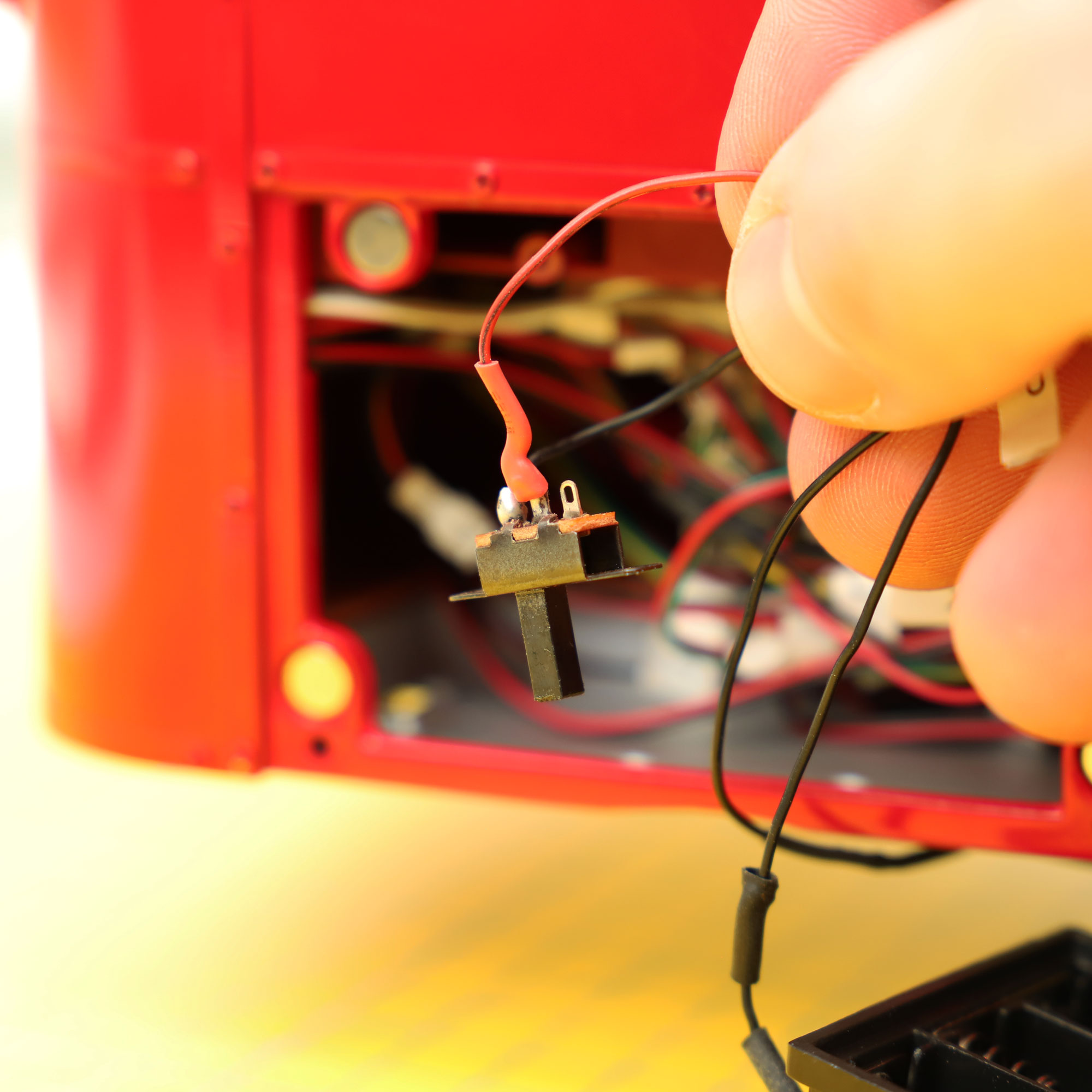
- Using a mini ratchet such as the Zyklop Mini Ratchet with PH0 bit, remove the 2 x UM screws holding the battery box switch in place. Unplug the battery box cable from the stock circuit board. The battery box and switch will no longer be required.
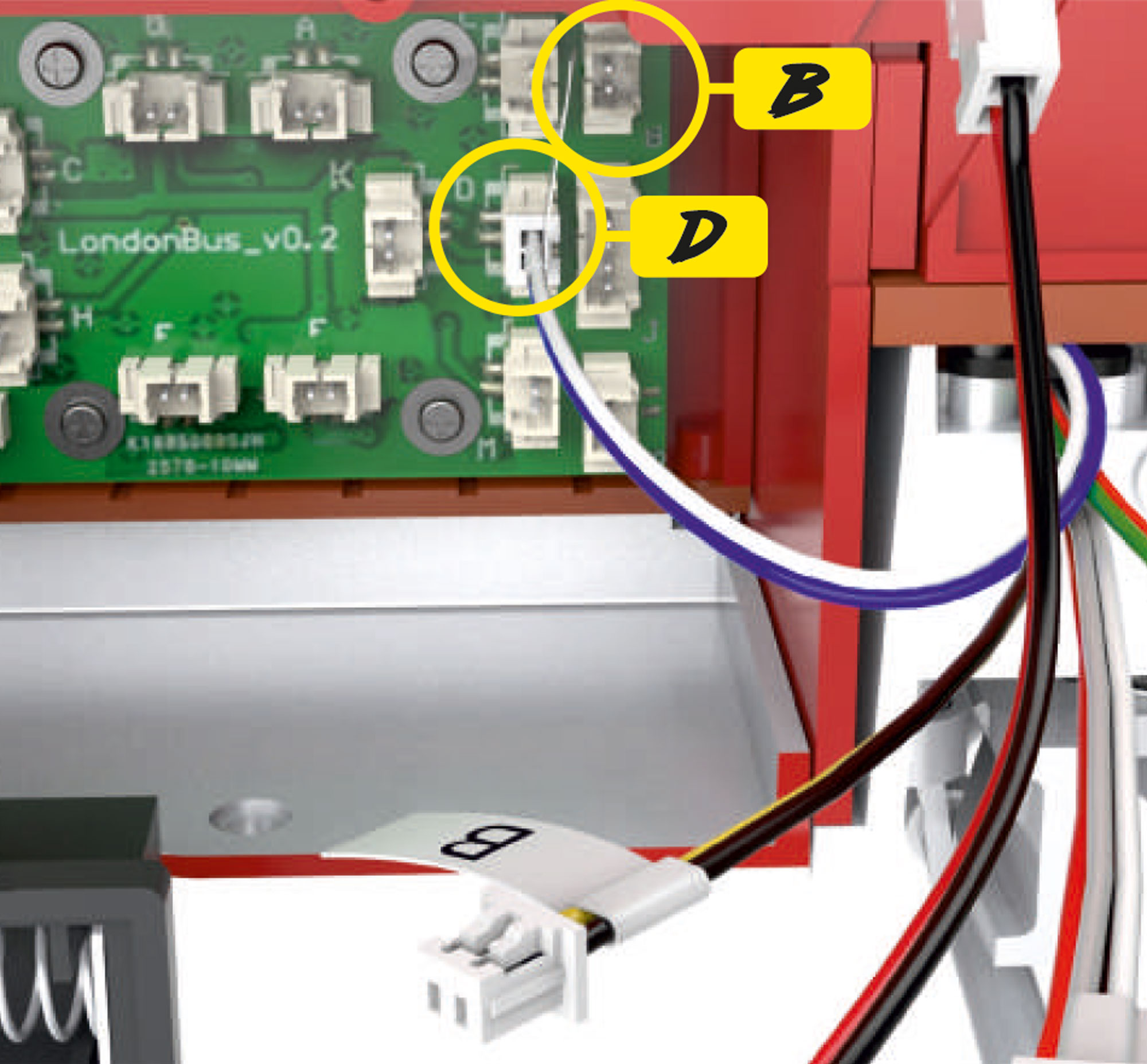
- Before removing the stock circuit board, unplug cables B (black and yellow) and D (white and blue). These cables are very short so need to be disconnected first.
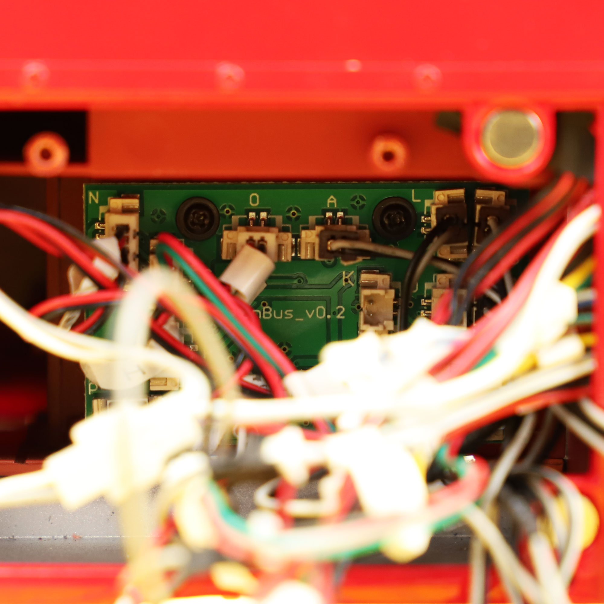
- Then, to make access to the board and identifying port numbers easier, remove the 4 x NP screws holding the stock circuit board in place and ease out of the battery compartment just enough to access the cables and ports.
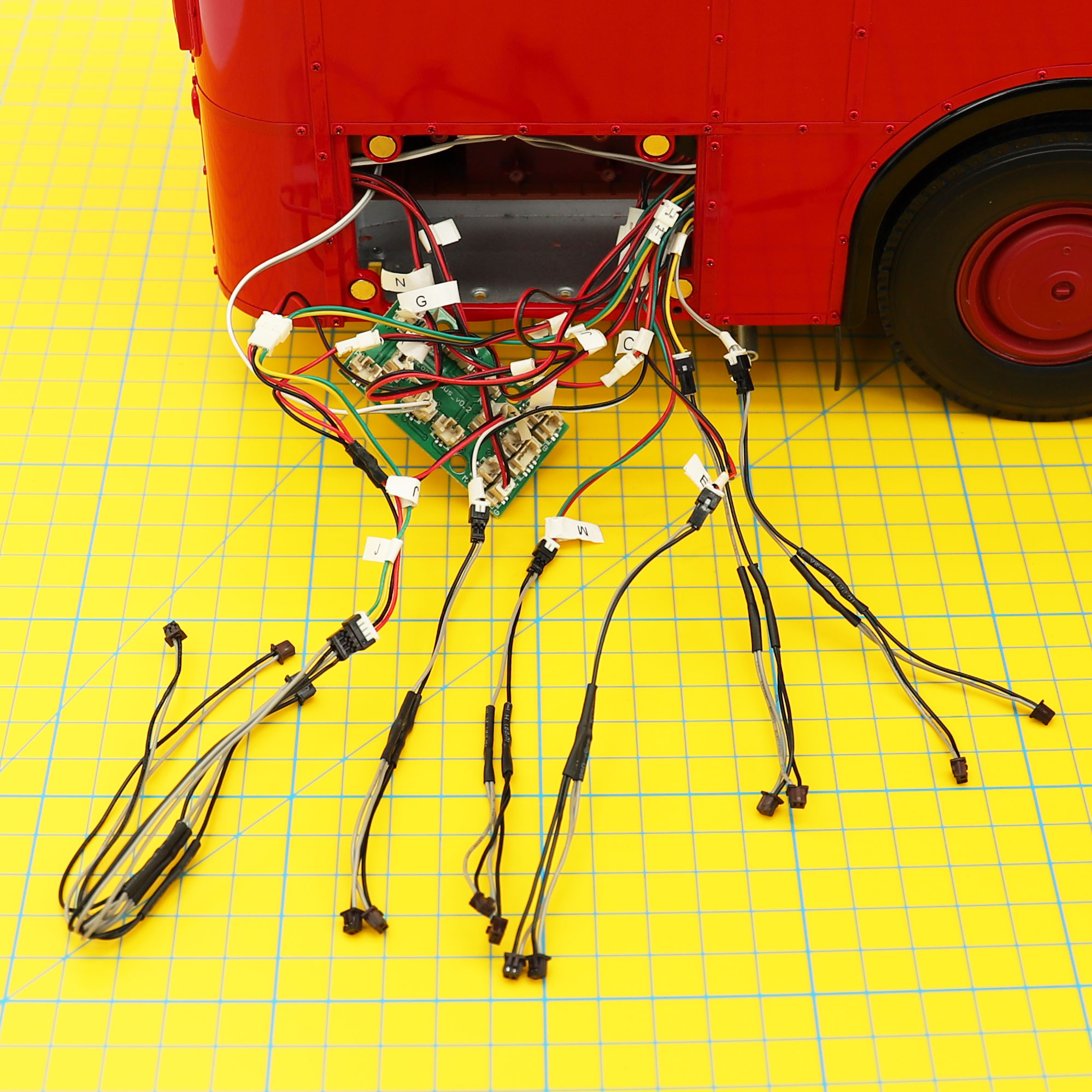
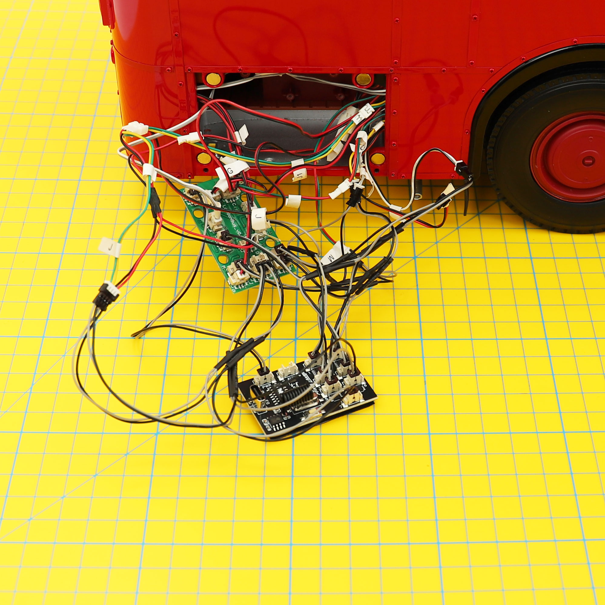
- Next, unplug cables A, E, J, L and M from the stock circuit board.
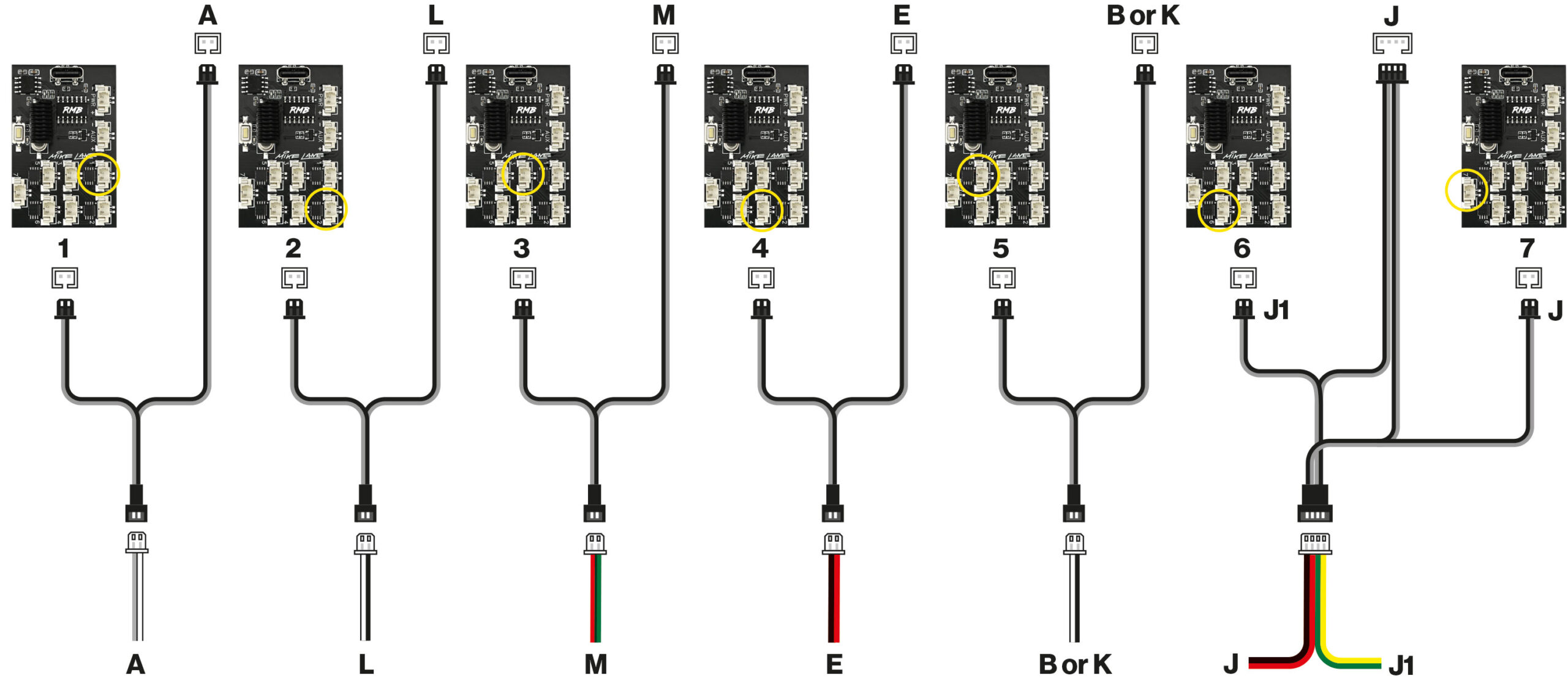
- Connect each of these cables to the socket end of the provided Y-splitter cables (J Connects to the large Y-splitter provided that has a 4 pin socket)
- Connect one plug end of each Y-splitter to the corresponding socket on the original board.
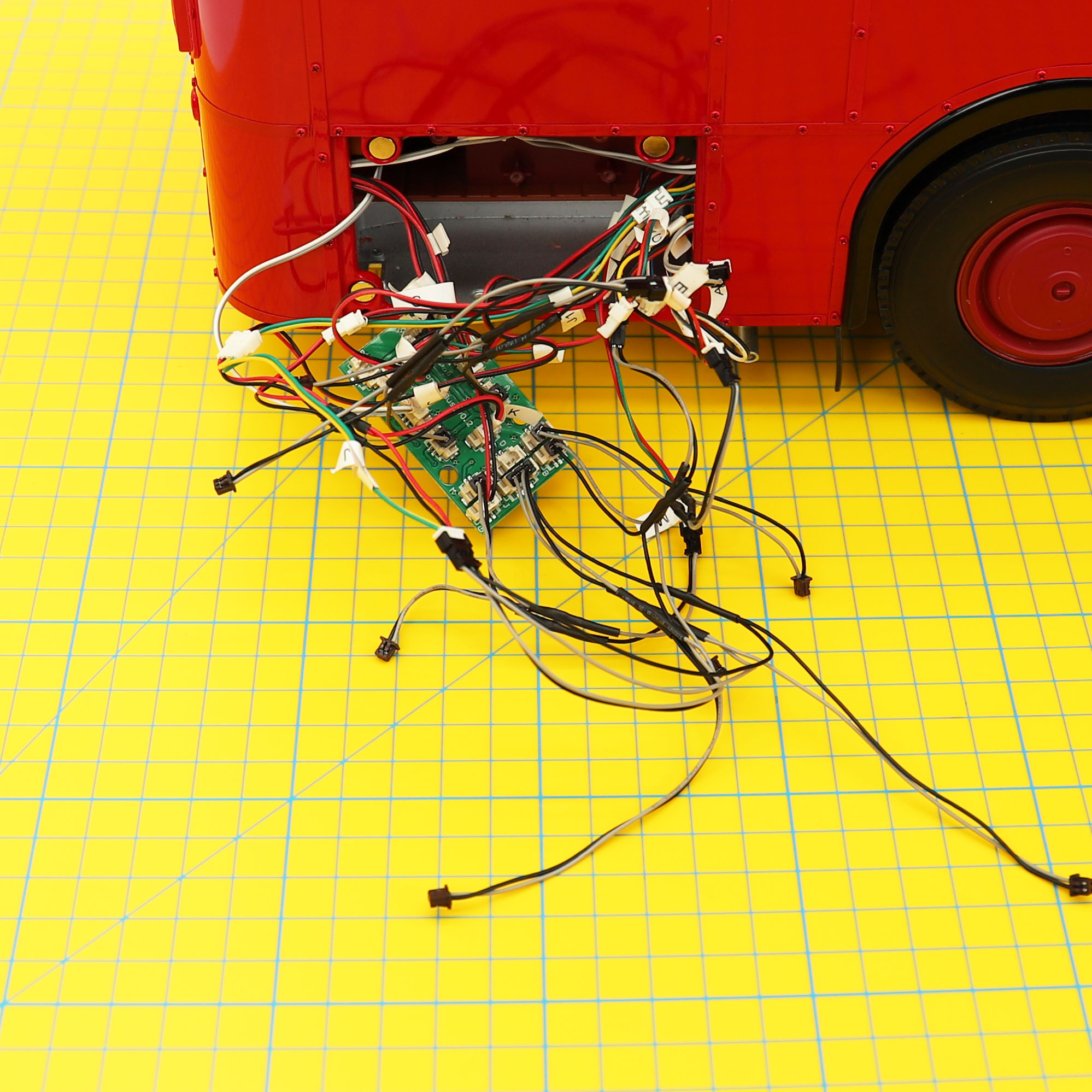
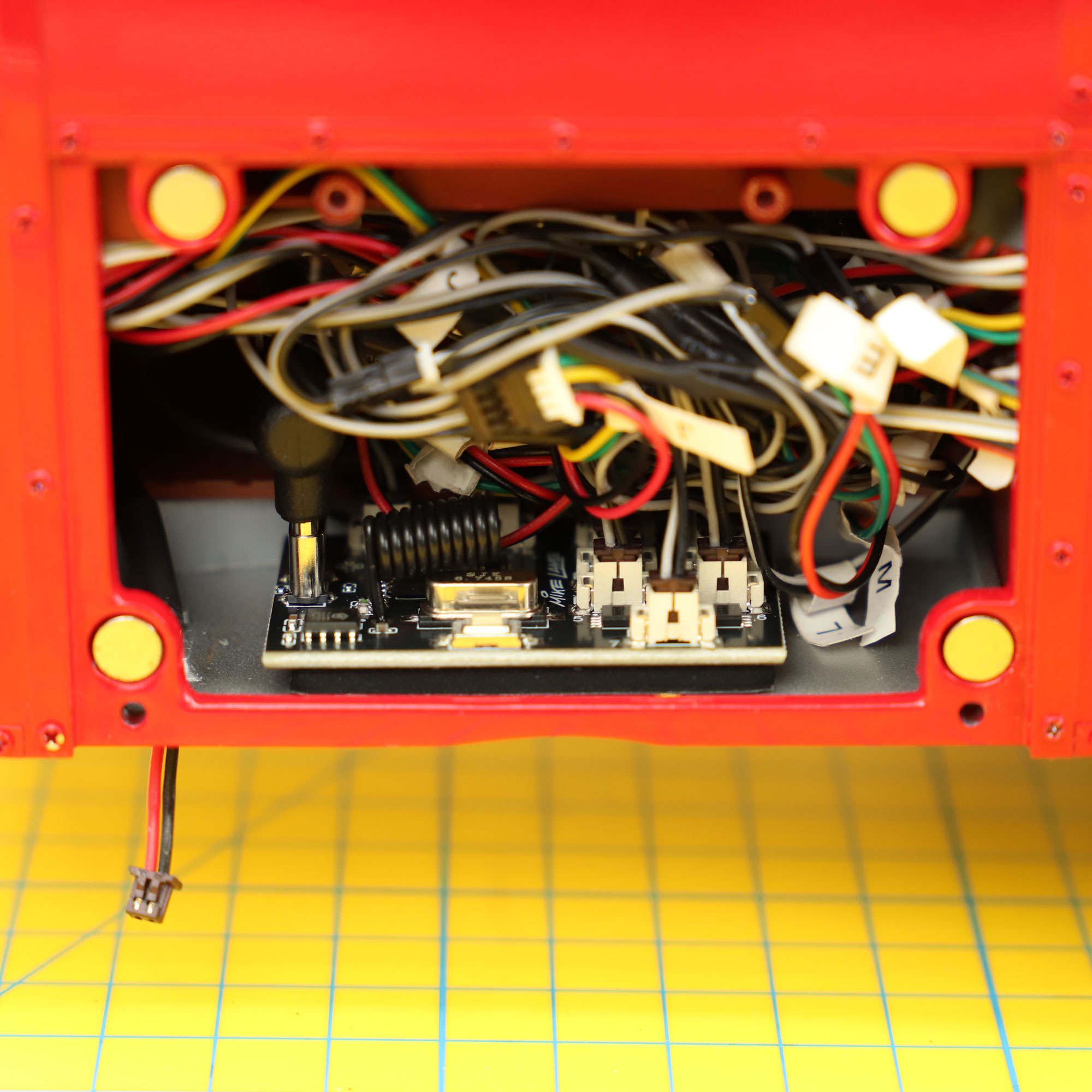
- Connect the remaining smaller plug of the Y-splitter cables Mike Lane Remote Control circuit board as follows:
| Stock Board | to | Mike Lane Remote Control Board |
| A | 1 | |
| L | 2 | |
| M | 3 | |
| E | 4 | |
| B for ‘Toot horn’ or K for ‘Klaxon sound’ (you choose!) | 5 | |
| J1 | 6 | |
| J | 7 |
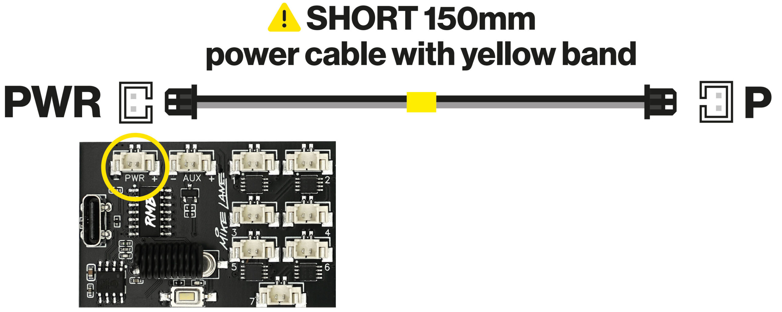
- Take the supplied SHORT 150mm power cable with the YELLOW BAND and connect one end to the stock circuit board socket P.
IMPORTANT: ONLY use the cable with the YELLOW BAND to connect PWR to A. If your cable is missing this band, you may have the wrong cable and whilst it may look similar it may damage your board if used.
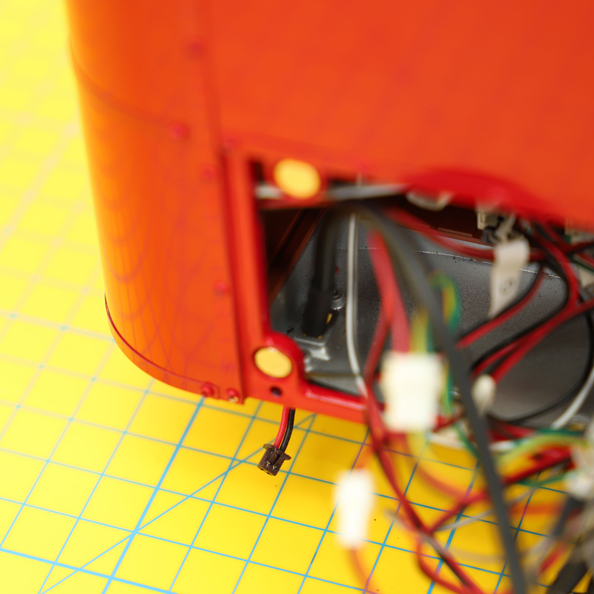
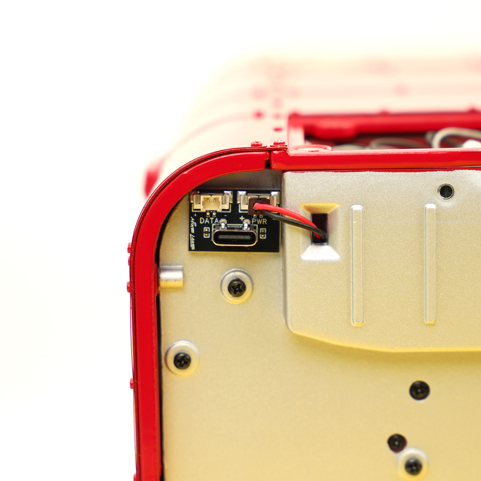
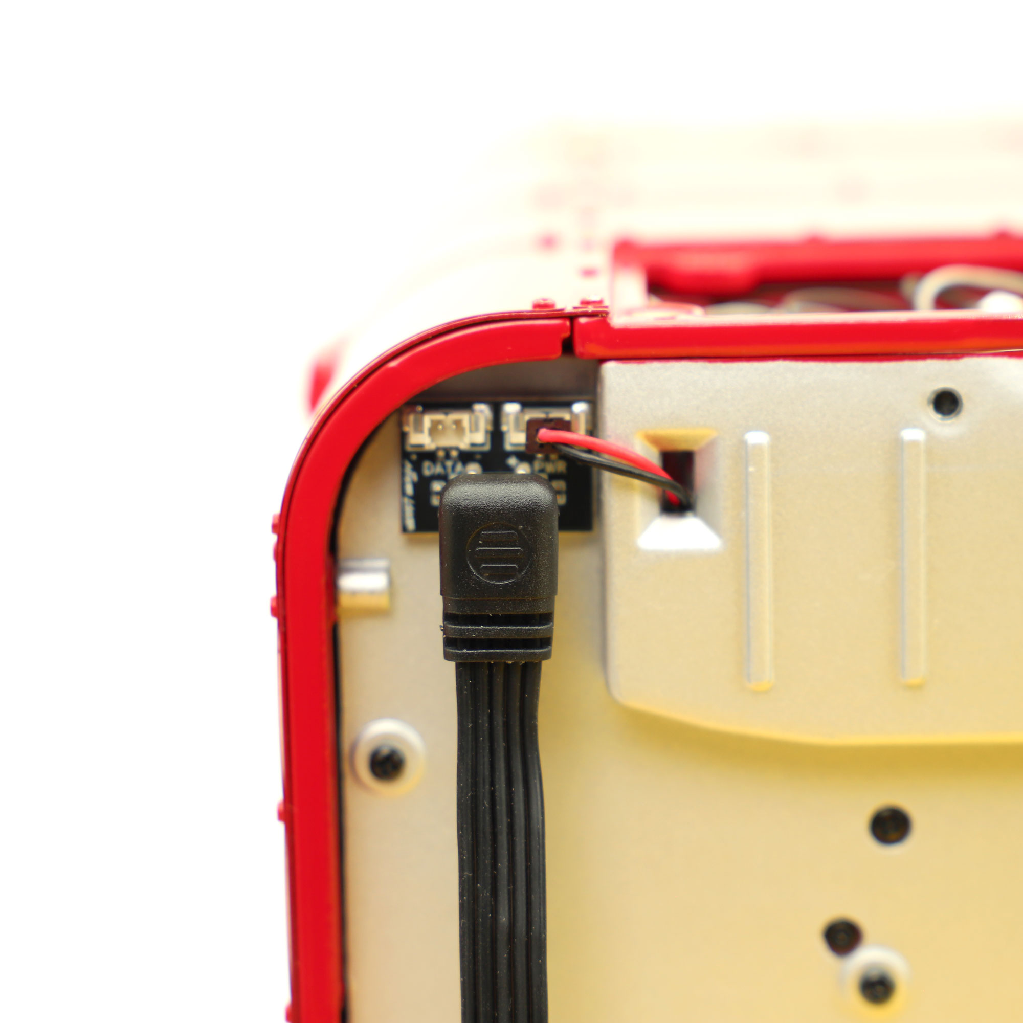
- Feed the end of the custom USB-to-JST cable provided (the end with the exposed red and black cable) out of the battery box switch hole. It may feel like a tight fit at first but it will fit through fine with some encouragement. You do not need to feed the whole of this cable through the hole, only the short red and black part.
- Connect the angled end of the USB-C cable to the Mike Lane Remote Control circuit board.
- Feed the cables neatly back into the model (there is a void at the back of the bus to curl the USB-C cable back into).
- Attach the Mike Lane Remote Control circuit board to the inside floor of the model using the supplied double-sided 3M pad.
- Using a pillow, carefully rest the model on it’s side so that you can clearly see the underside.
The installation is now complete!
The AUX port
The AUX port on the Mike Lane Remote Control circuit board provides a 5v output at 1.5amp (max) – switchable via AUX button on the remote.
This port provides plenty of power and flexibility for potential customisations and third-party mods – or practically anything else you need power for inside your model!
The AUX port will also be able to support future Mike Lane accessories which we have planned for the model.
Endless possibilities
By design, the Mike Lane Remote Control Power Mod is a powerful and flexible device, with the ability to power your own customisations, future Mike Lane add-ons and third-party mods via the AUX socket.
If you have any special requests or have a requirement to power something not catered for by the adaptor cables in the box, please get in touch – we most likely already have a solution available for you!
Polarity Warning
IMPORTANT: When connecting any 3rd party accessories using the supplied adaptor cables, ensure to check that the grey cable connects to positive and the black to negative.
Incorrect polarity to the AUX port will damage either or both boards and will void the warranty.
Use of third-party accessories and mods is entirely at the owners risk as not all third-party mods have been tested with this device. Please refer to manual before use and always check compatibility.
This upgrade features a special action sequence, programmed especially for this model and utilising all of its existing lights and sound effects – adding something entirely new to your model!
This action sequence simulates the bus slowly coming to life. Cabin lights illuminating as the driver jumps onboard, the brake lights come on before the engine is started. Headlights light up the road ahead and the brake lights go out as the bus starts its early morning route. The destination boards light up to advertise the route before the bell sounds as the conductor spots the first of the day’s eager passengers.


