Preparing KITT for the

Ultimate Electronic Kit

Preparing KITT

for the Ultimate Electronic Kit

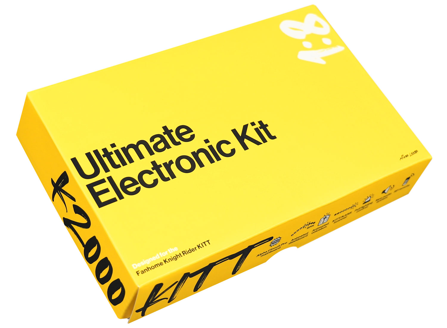
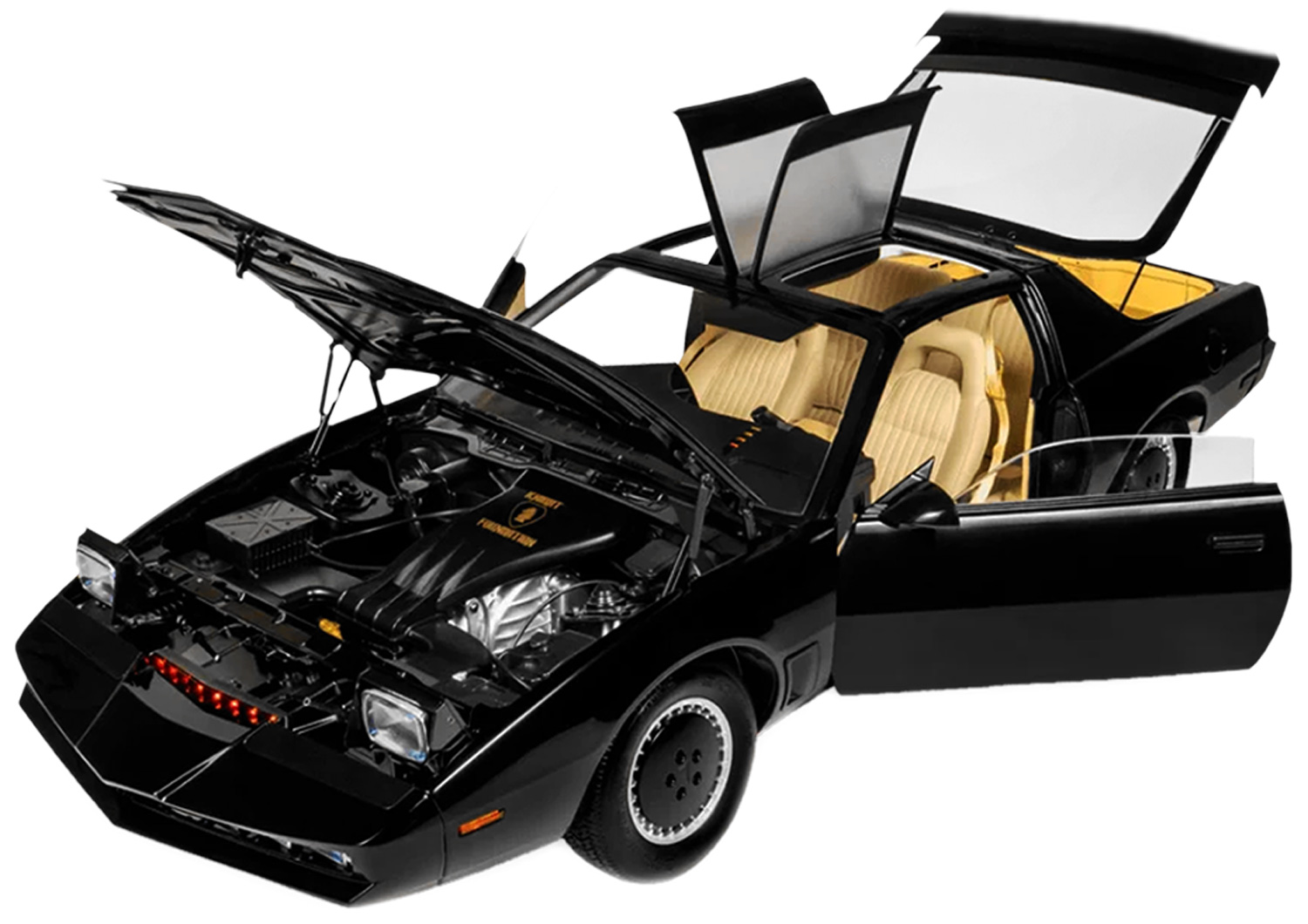
Designed for the Build the K2000 Knight Rider KITT from Fanhome/DeAgostini/Altaya. 

Power Requirements

Power Requirements

The Alpha Circuit Pro mainboard within this kit can be powered by practically anything with a USB-C connection and will power the entire model. However, to provide enough power to the whole model and support all its features, a USB-C power adaptor with 4.5v-6v DC Output at a minimum 2A (10W) is recommended.

A 2M braided USB-C cable is included with the kit, however you will need to provide your own USB-C adaptor.

An Amazon search for 5V 2A USB-C usually returns suitable adaptors, but please double-check the ratings before use.

Once the Ultimate Electronic Kit is installed, you will be able to power KITT via any one of these methods:

Via a USB-C power adaptor (Recommended)
Via a USB-C rechargeable power bank
Via a USB-C port on a Laptop, PC or Mac

You must not attempt to power the model via any other method, including:

The existing AAA battery box
Third-party power mods or alternative power sources
The in-built power mod on the Dashboard Monitors (the Alpha Circuit Pro’s USB-C power supply replaces the need for this)

Preparing the car

Preparing the car

New builds

If you’re a new subscriber or have yet to start building KITT, excluding some early parts listed below, you can build up to Issue 42 before the Ultimate Electronic Kit comes into effect.

The parts to exclude from your build during the stages leading up to Issue 42 are as follows:

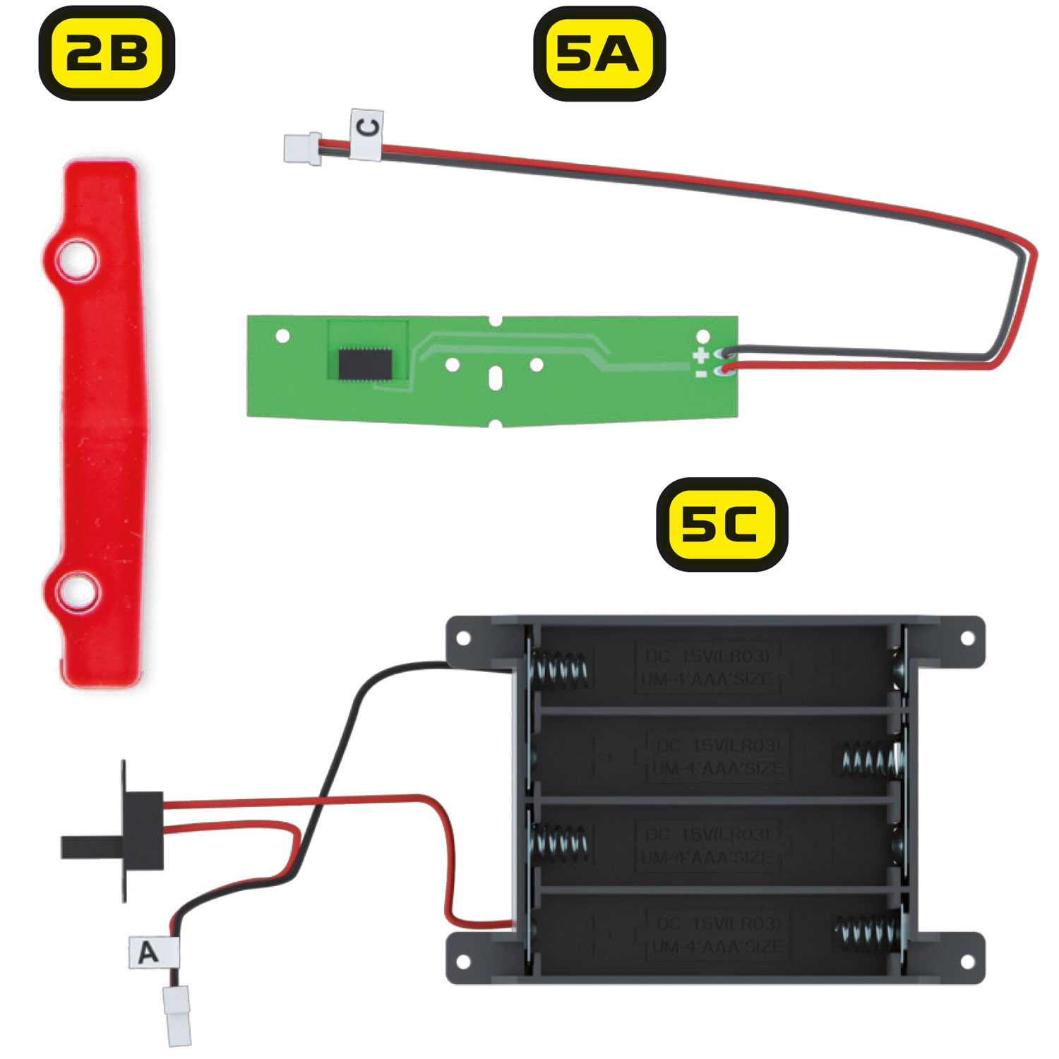
Stage 02:

  • 2B – Scanner lens

Stage 05:

  • 5A – Scanner circuit board
  • 5C – Battery box

These components will not be reused.

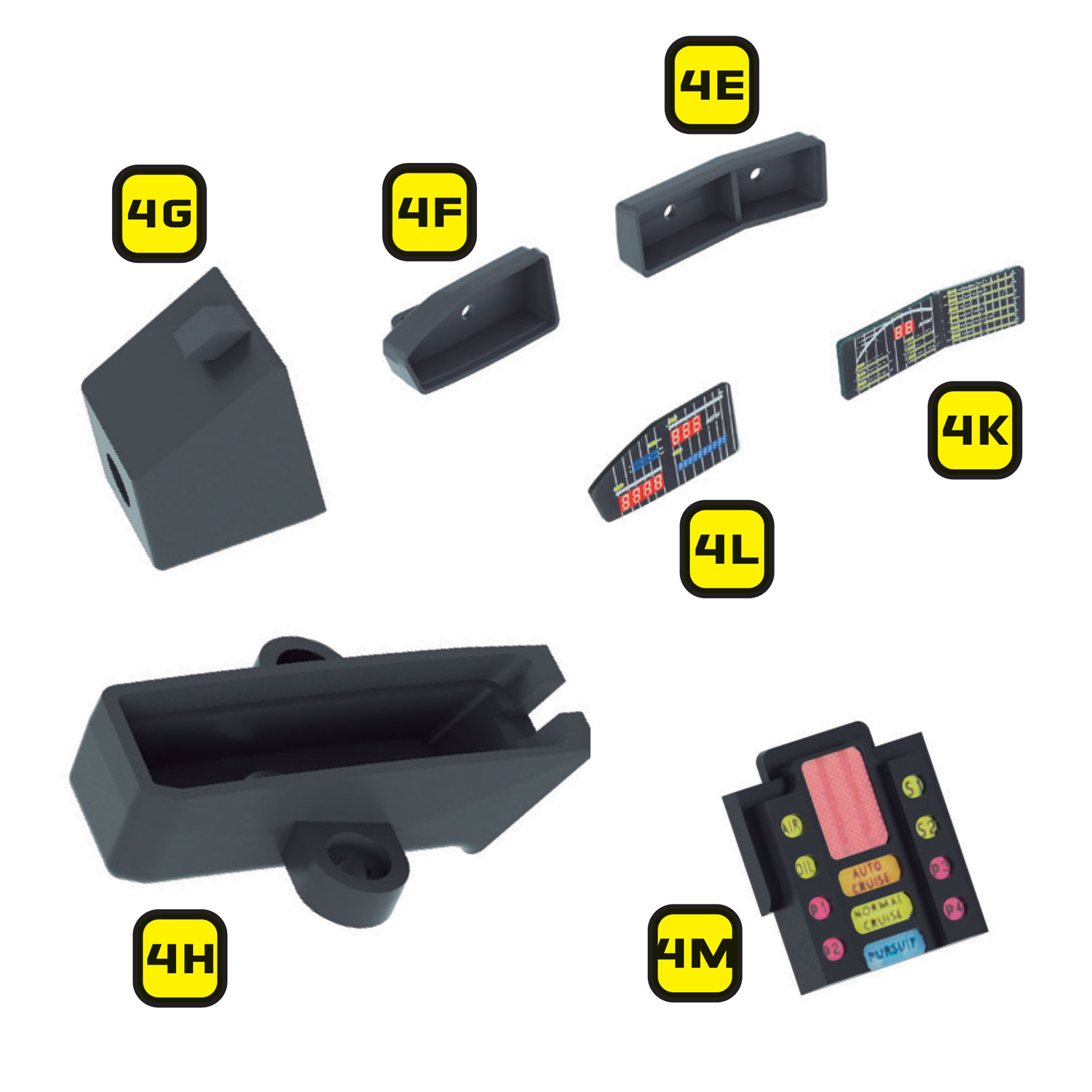
Remove components 4E 4F, 4G, 4H, 4K, 4L, 4M

You can also exclude the following parts from the dashboard:

Stage 04:

  • 4E – Right instrument housing
  • 4F – Left instrument housing
  • 4G – K.I.T.T voice box
  • 4H – Start-up panel bracket
  • 4K – Right instrument panel
  • 4L – Left instrument panel
  • 4M – Front panel of K.I.T.T voice box

These components will not be reused.

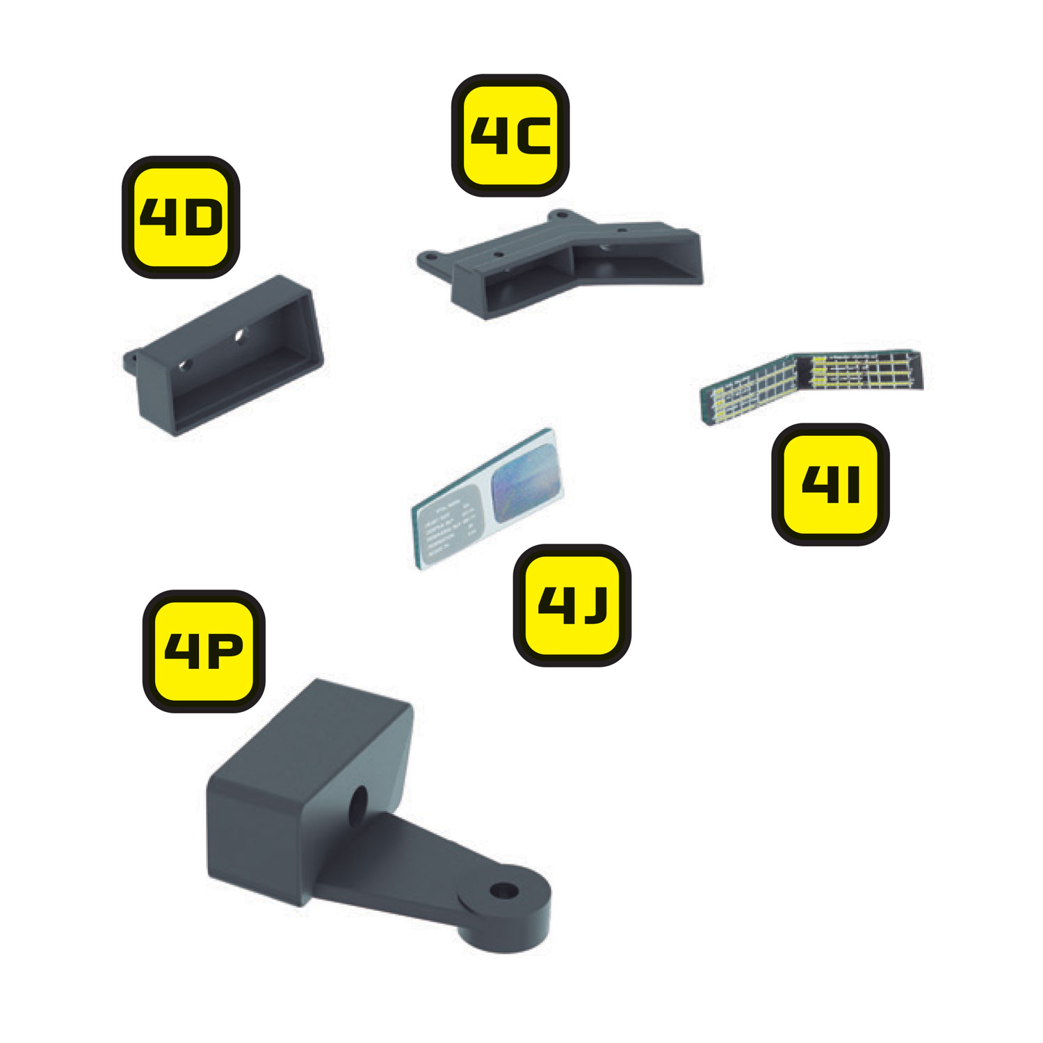
Remove components 4C, 4D, 4I, 4J, 4P

If you have purchased the Mike Lane Dashboard Monitors, then you can also exclude:

Stage 04:

  • 4C – Lower right dash housing
  • 4I – Lower instrument panel
  • 4D – Monitor housing
  • 4J – Monitor screens
  • 4P – Lower right button panel housing

These components will not be reused.

Excluding these parts, you are free to build up to Issue 42 where the Pro Speaker and Alpha Circuit Pro are installed in place of the stock speaker and mainboard. You can also skip to ‘Preparing the Mike Lane Dashboard Monitors – Firmware upgrade’.

Part or complete builds

The Ultimate Electronic Kit is designed to be installed at Stage 42 onwards. You will need access to the underside of the dashboard, the underside of the interior floor panel, the front nose, and the front and rear outer wings.
  Disassembling your model

If you have built past Stage 42, or even completed your model, you will need to disassemble your model by carefully following the original magazines and build instructions – but in reverse.

Carefully bag and tag each component that you disassemble, labelling the issue number and part numbers on each bag to make it easier to reassemble later.

You will not need to disassemble every component or assembly. You will only need to disassemble the required sections to give you the access you require to install this modification.

Remove rear floor panel of KITT model

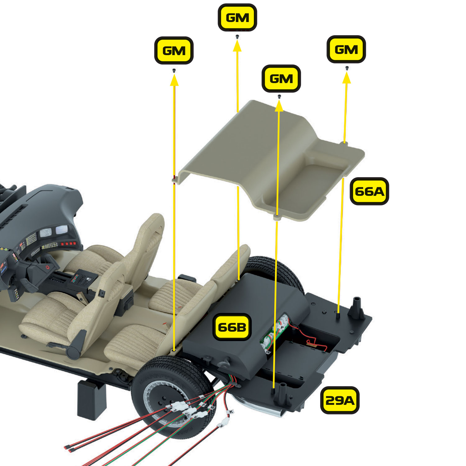
If you have already reached Stage 67, remove the rear floor panel (66A) and set it aside along with the GM screws for refitting later.

Removing KITT's fuel tank cover and fuel tank filler pipe

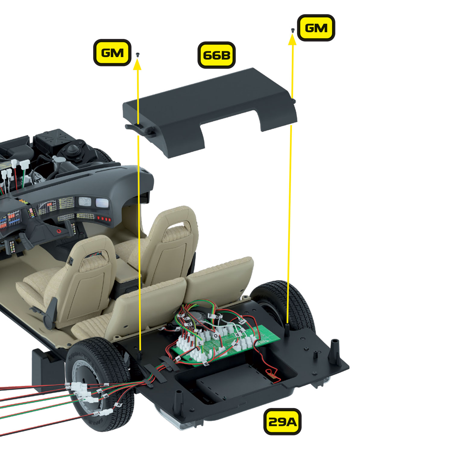
Remove the fuel tank cover (66B) and fuel tank filler pipe (66C). These items will not be refitted as they will interfere with the Pro Speaker and Alpha Circuit Pro.

Removing KITT's original speaker and speaker box

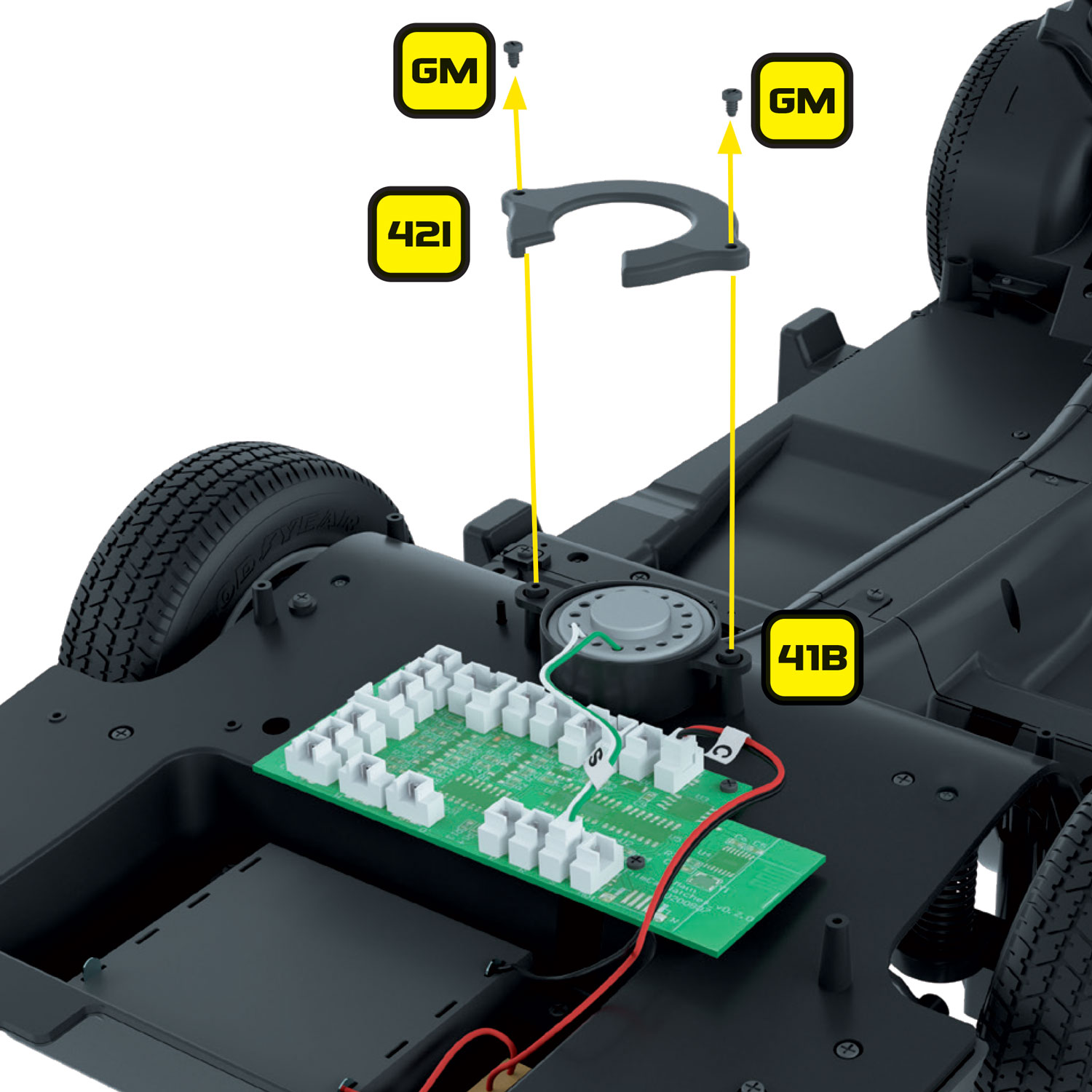
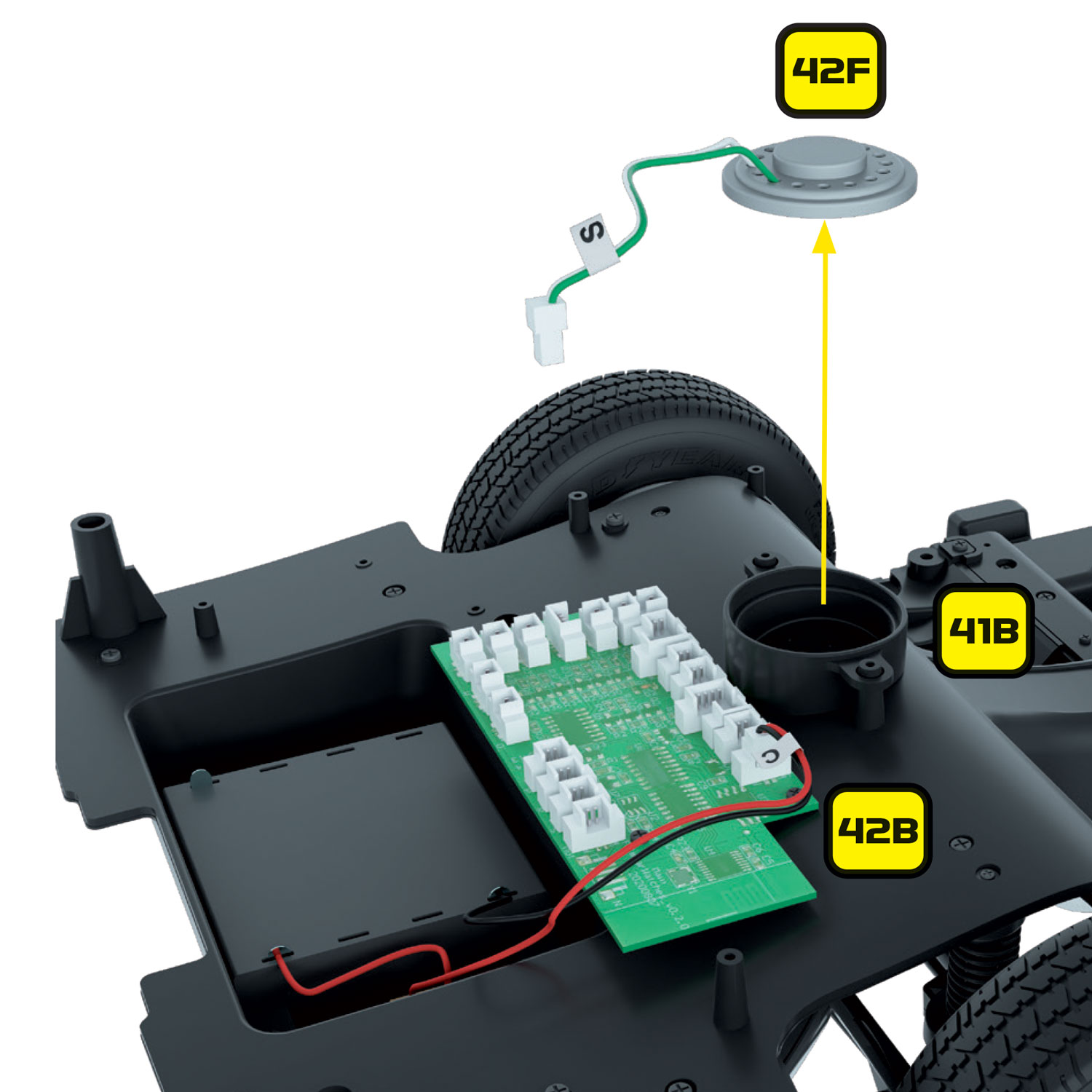
Remove the original speaker (42F) and speaker box (41B) by unscrewing the 2 x GM screws on either side and retain the screws and cover plate, as they will be reused.

Removing KITT's original speaker and speaker box to replace with ProSpeaker

The original speaker (42F) and speaker box (41B) will no longer be required and will be replaced with the Pro Speaker.

Removing KITT's original circuit board

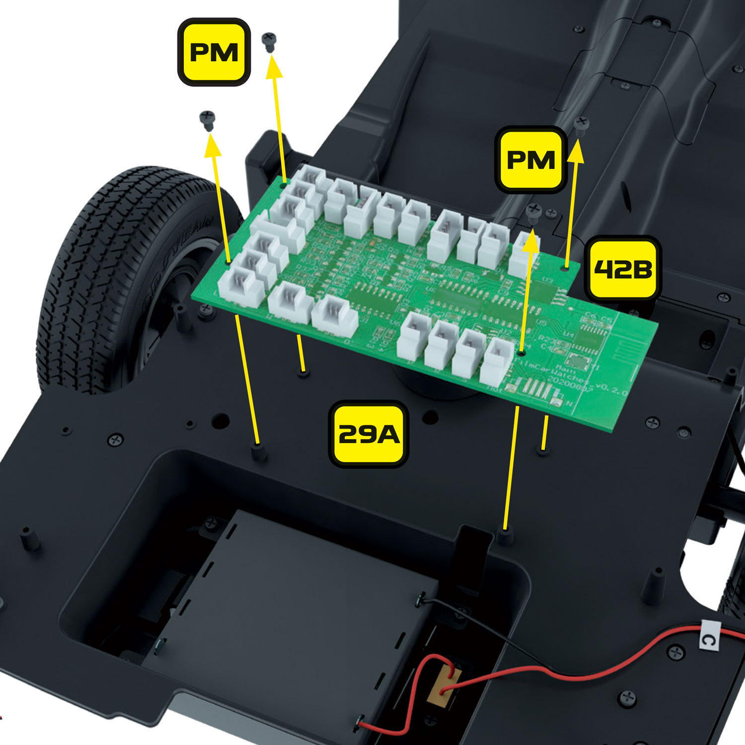
Carefully unplug all the cables from the original circuit board (42B).

With all the cables removed, unscrew the 4 x PM screws that hold the circuit board in place and keep them safe as they will be reused. Remove the original circuit board, this is no longer required.

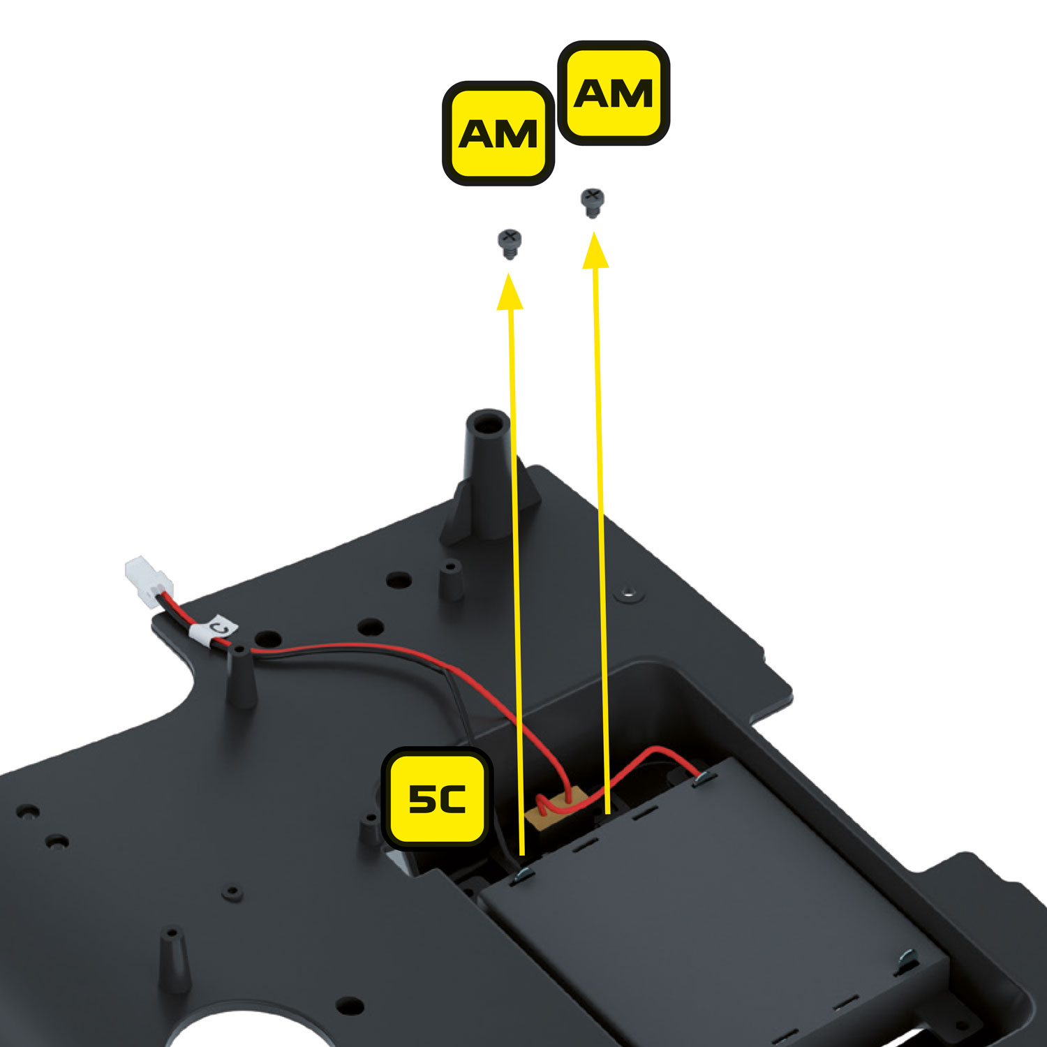
Remove the 2 x AM screws holding the battery box switch (5C) into position.

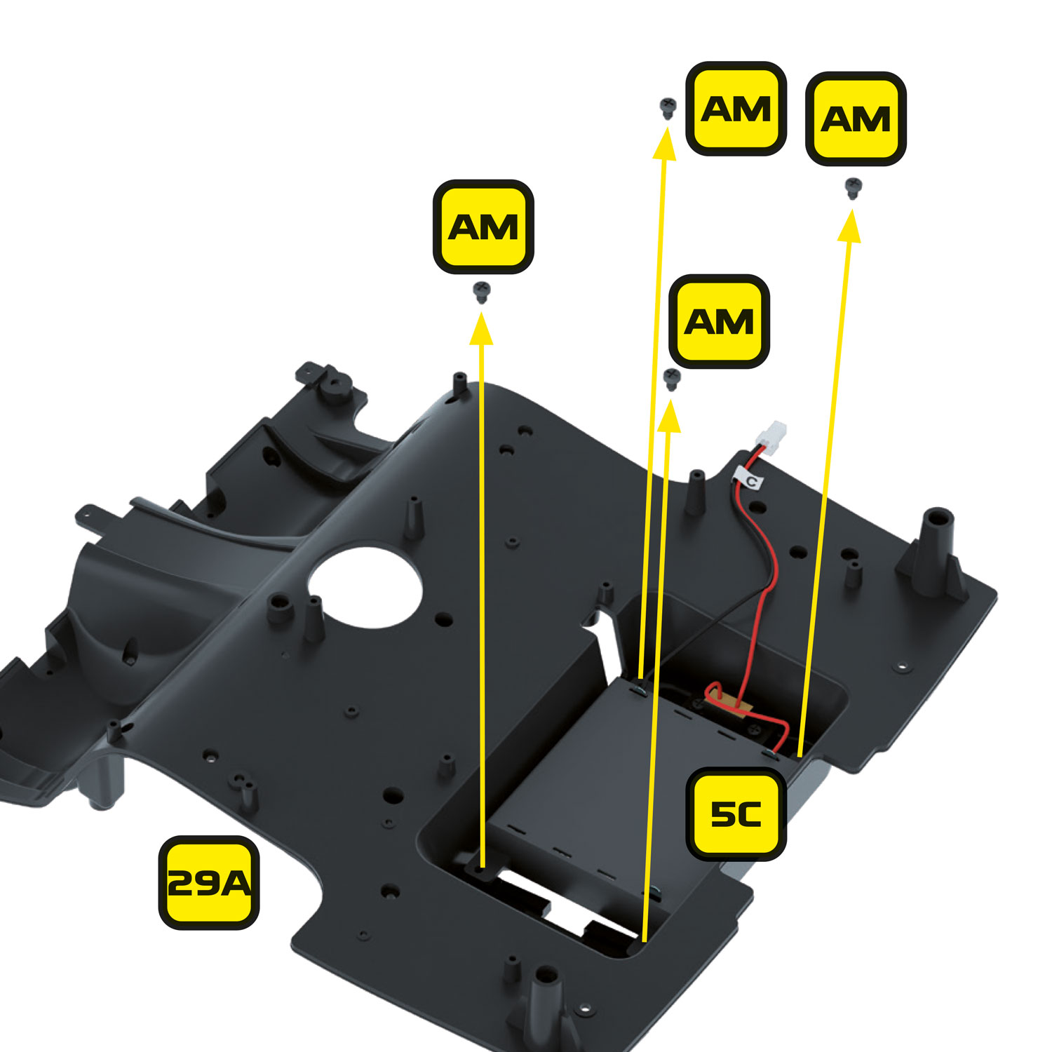
Remove the 4 x AM remaining screws holding the battery box (5C) into position. We will no longer be using the battery box but will be reusing the battery box cover.

The chassis is now ready to take the Alpha Circuit Pro and Pro Speaker.

Preparing the dashboard

Preparing the dashboard

Retrieving KITT's dashboard

Retrieve the dashboard from Stage 04.

Removing dashboard if mounted onto inner floor

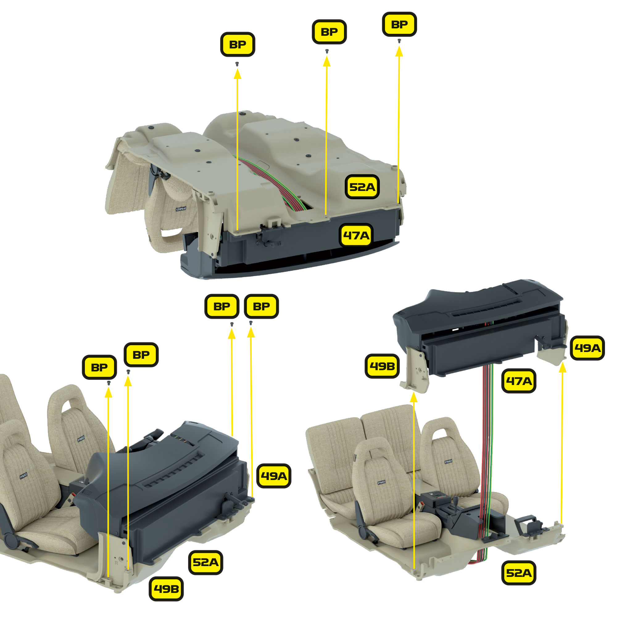
If it is already mounted onto the inner floor at Stage 65, then remove it by unscrewing the 3 x BP screws on the underside, and the 2 x BP screws on either side.

Removing KITT's front interior panels

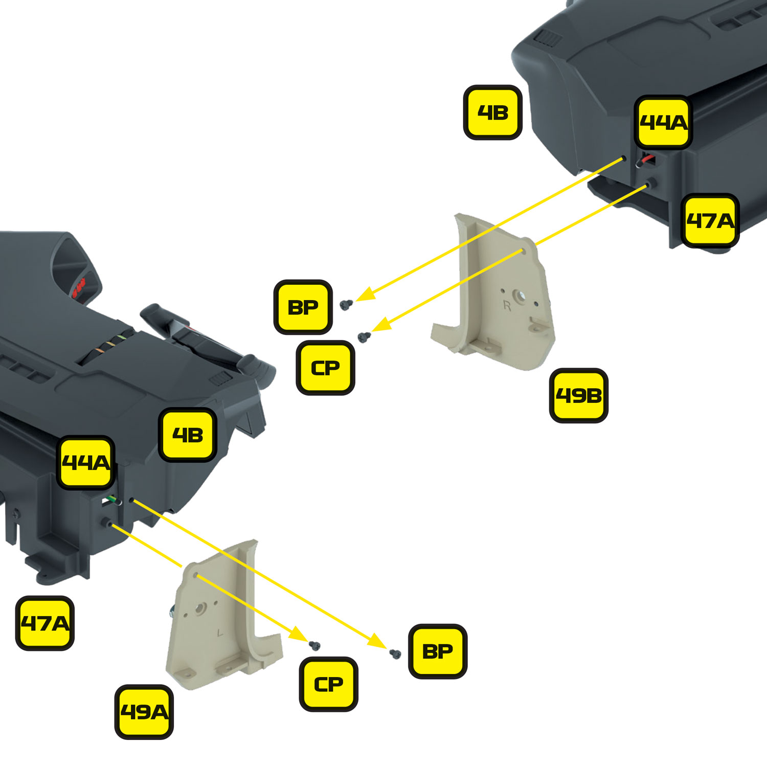
If you have already reached Stage 49, remove the front interior panels (49A and 49B) from the dashboard.

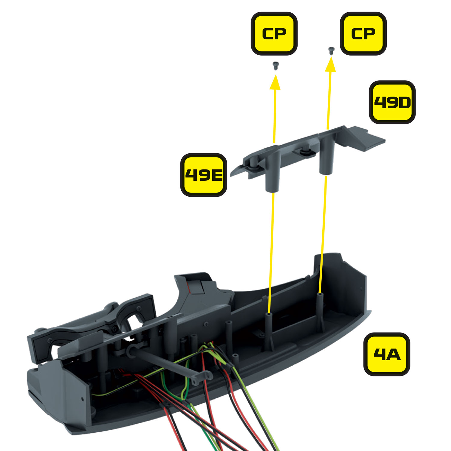
Removing passenger dash panels 49D and 49E

Then remove the passenger dash panels (49D and 49E). Carefully place these and their associated screws to one side for refitting later.

Removing lower facia panel and dashboard rear panel from dashboard

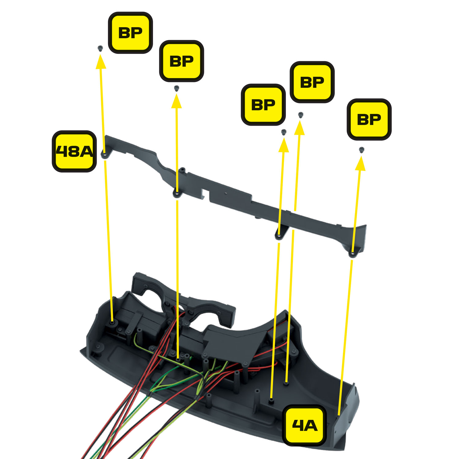
Remove the lower facia panel (48A) and dashboard rear panel (48F) from the dashboard as installed in Stage 48. Carefully place these and their associated screws to one side for refitting later.

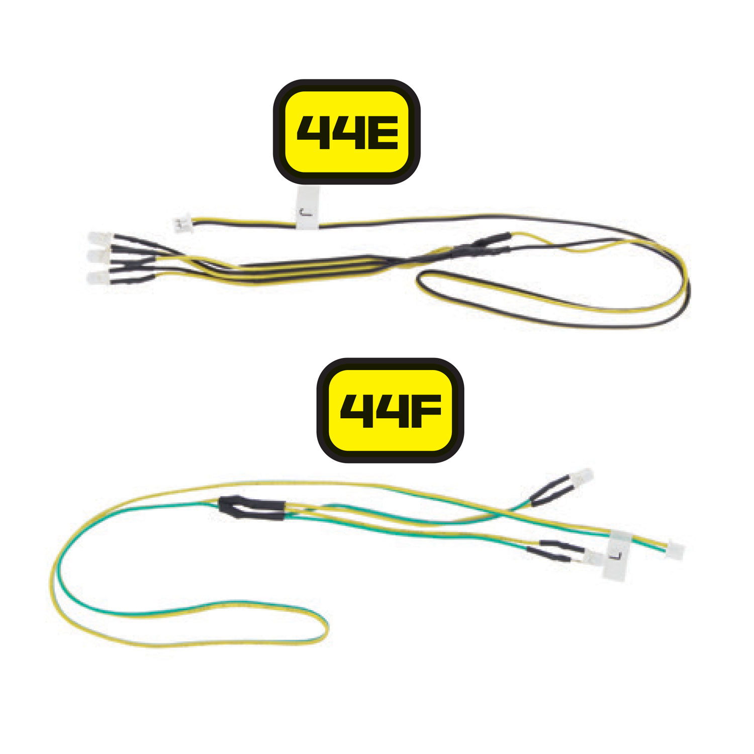
Removing original electrical cables 44E and 44F

Some of the original electrical cables are no longer required and can be removed. These are:

  • 44E – Dashboard instrument panel 1 wire and lights – marked ‘J
  • 44F – Dashboard instrument panel 2 wire and lights – marked ‘L
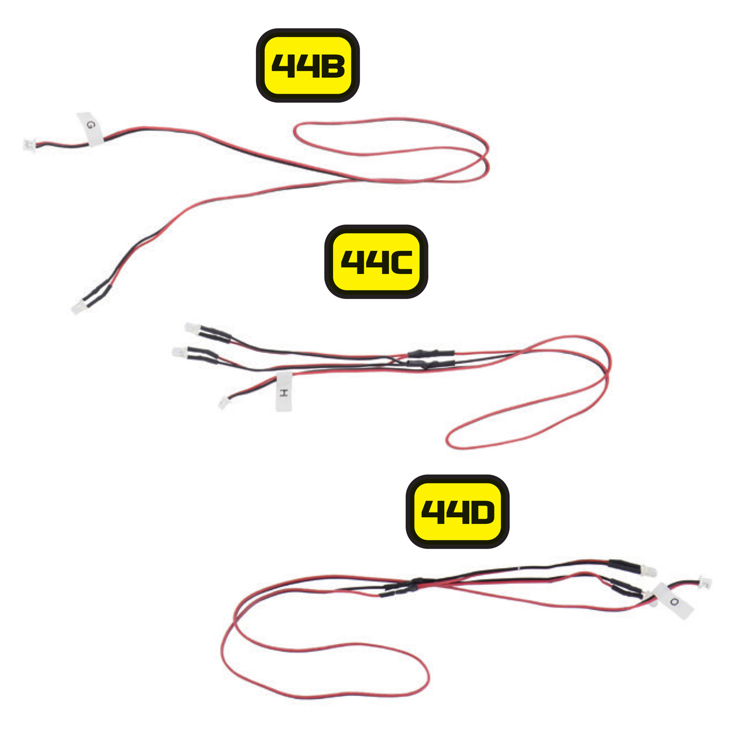
Removing cables 44B, 44C and 44D

If you have purchased the Mike Lane Dashboard Monitors, then you can also remove:

  • 44B – Keypad wire and lights – marked ‘G
  • 44C – Dashboard monitor lights – marked ‘H
  • 44D – Front panel wire and voice box lights – marked ‘O
Removing lower right dashboard housing

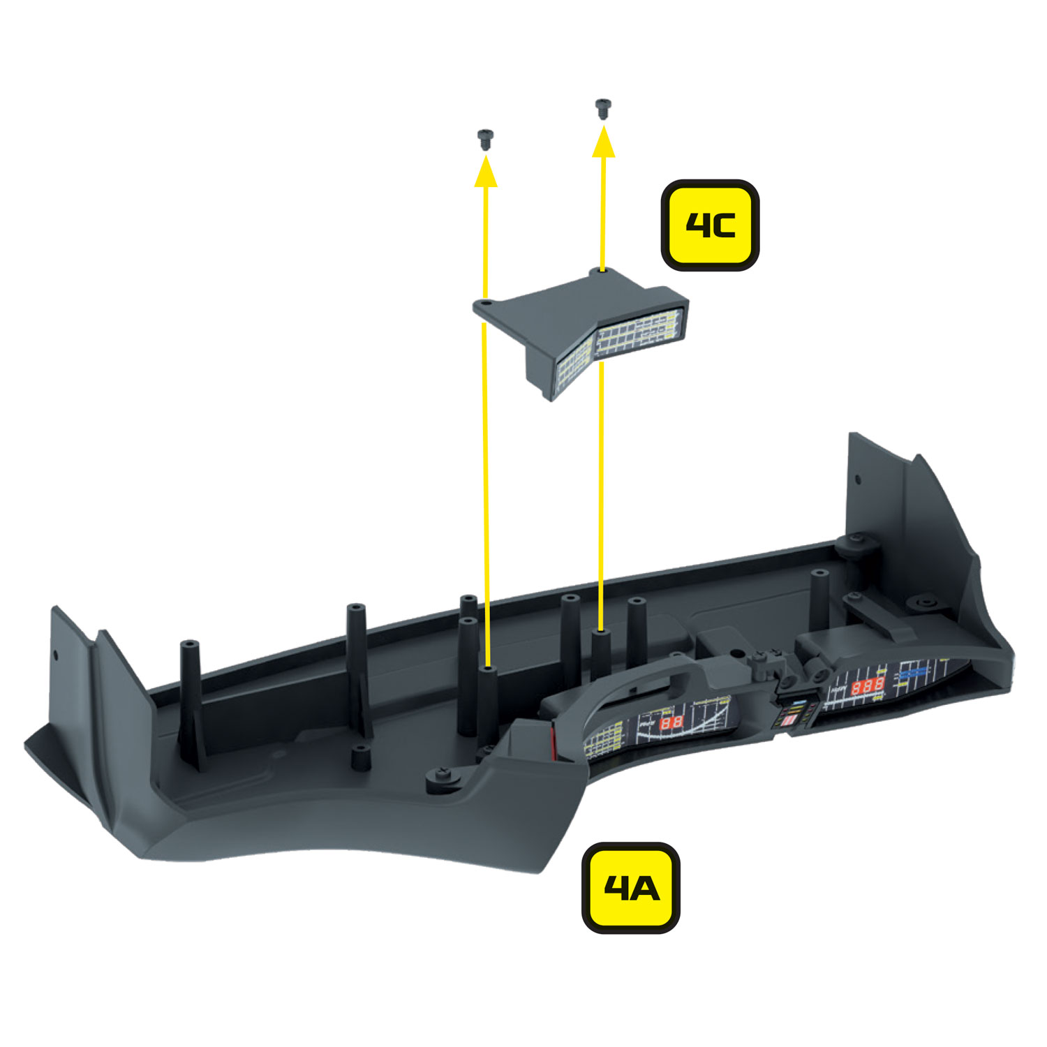
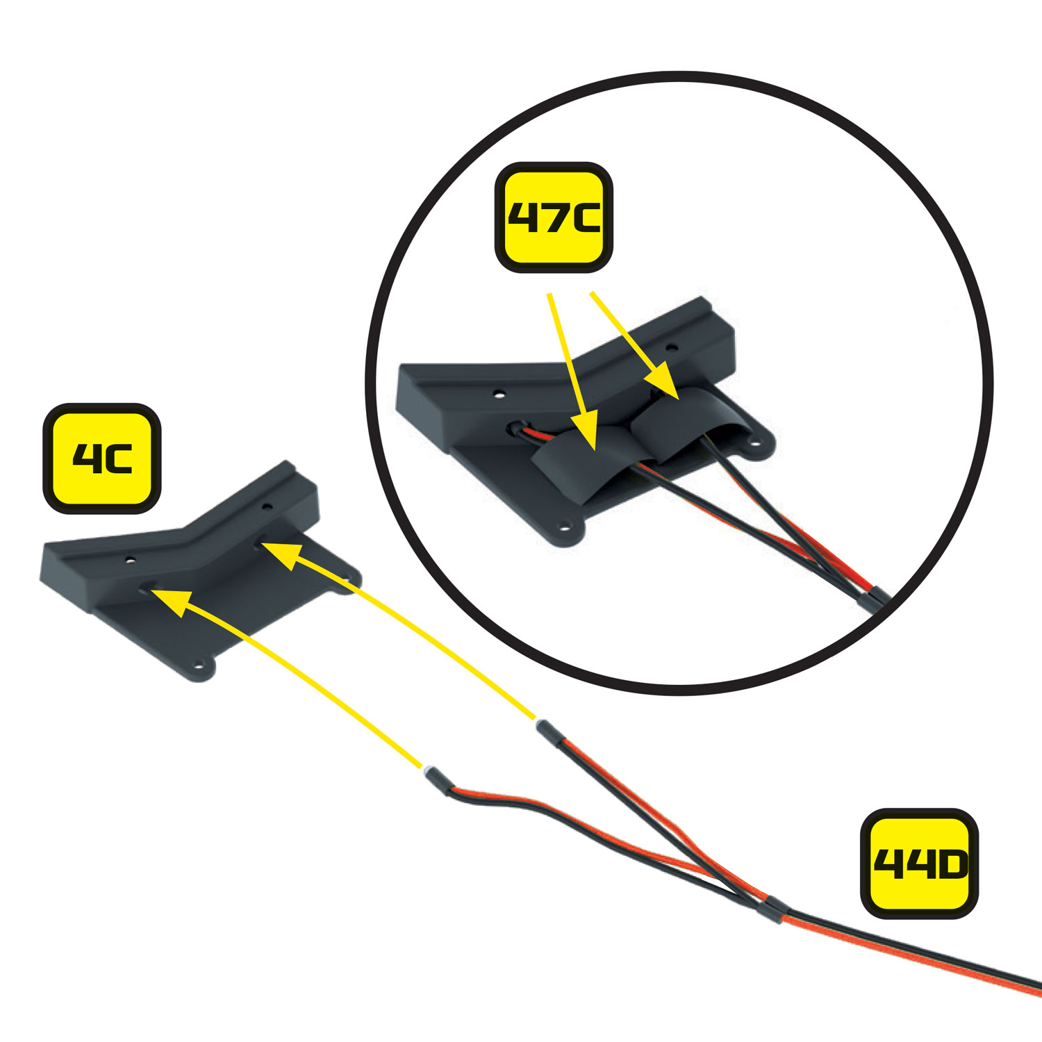
Remove the lower right dashboard housing (4C).

Inserting LEDs into lower right dashboard housing

If you are not fitting the Mike Lane Dashboard Monitors then take the 2 x LEDs on the cable labelled ‘O’ (44D) (originally intended for the voice box section) and insert them in the lower right dashboard housing (4C). Keep to one side for refitting into the dashboard later.

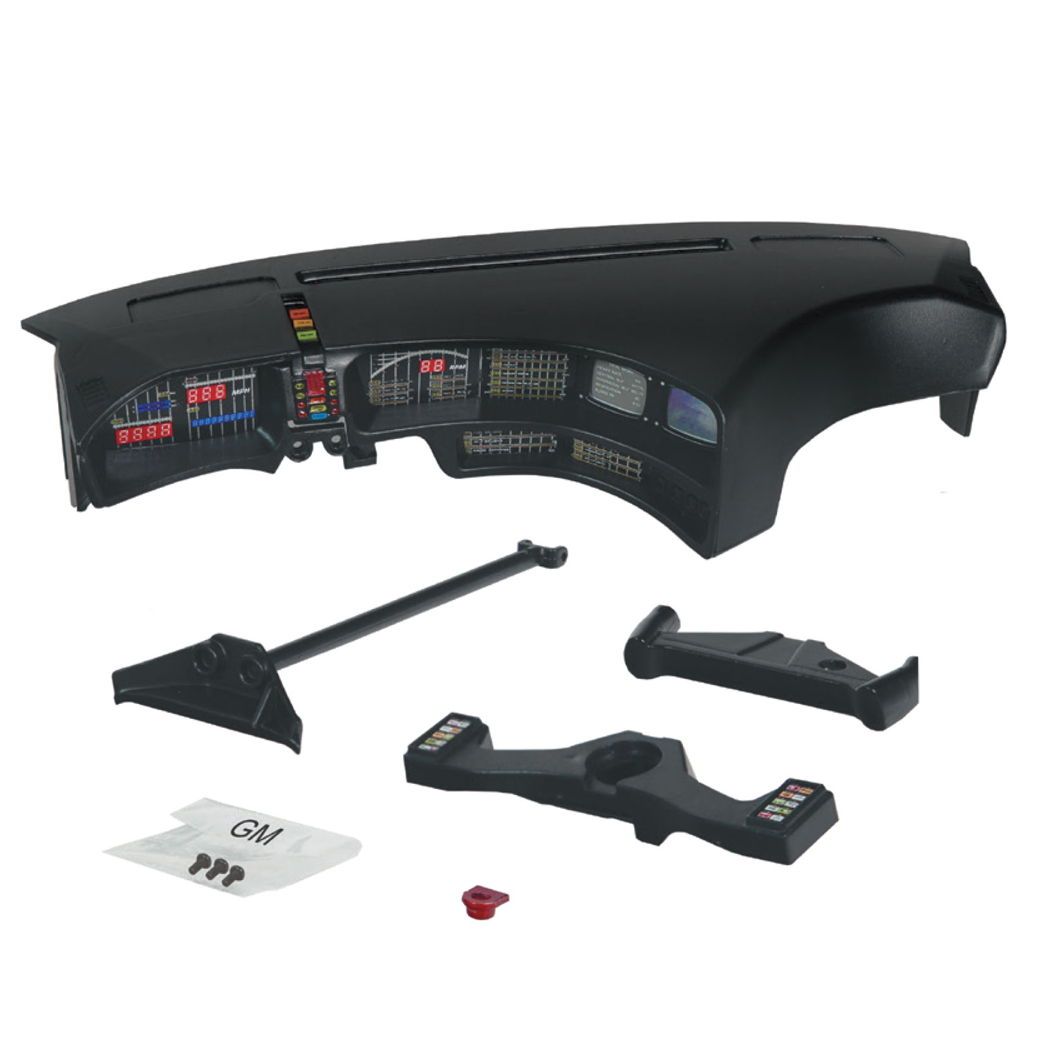
Remove components 4E 4F, 4G, 4H, 4K, 4L, 4M

Remove the following parts previously installed in Stage 04 of the build.

  • 4E – Right instrument housing
  • 4F – Left instrument housing
  • 4G – K.I.T.T voice box
  • 4H – Start-up panel bracket
  • 4K – Right instrument panel
  • 4L – Left instrument panel
  • 4M – Front panel of K.I.T.T voice box

These components will not be reused.

Remove components 4C, 4D, 4I, 4J, 4P

If you have purchased the Mike Lane Dashboard Monitors, then you can also remove:

  • 4C – Lower right dash housing
  • 4I – Lower instrument panel
  • 4D – Monitor housing
  • 4J – Monitor screens
  • 4P – Lower right button panel housing

These components will not be reused.

Cables that need to remove

If you have already installed the Mike Lane Dashboard Monitors, please remove them for the installation of the lower dash flexible circuit board and panel.

The following items need to be removed:

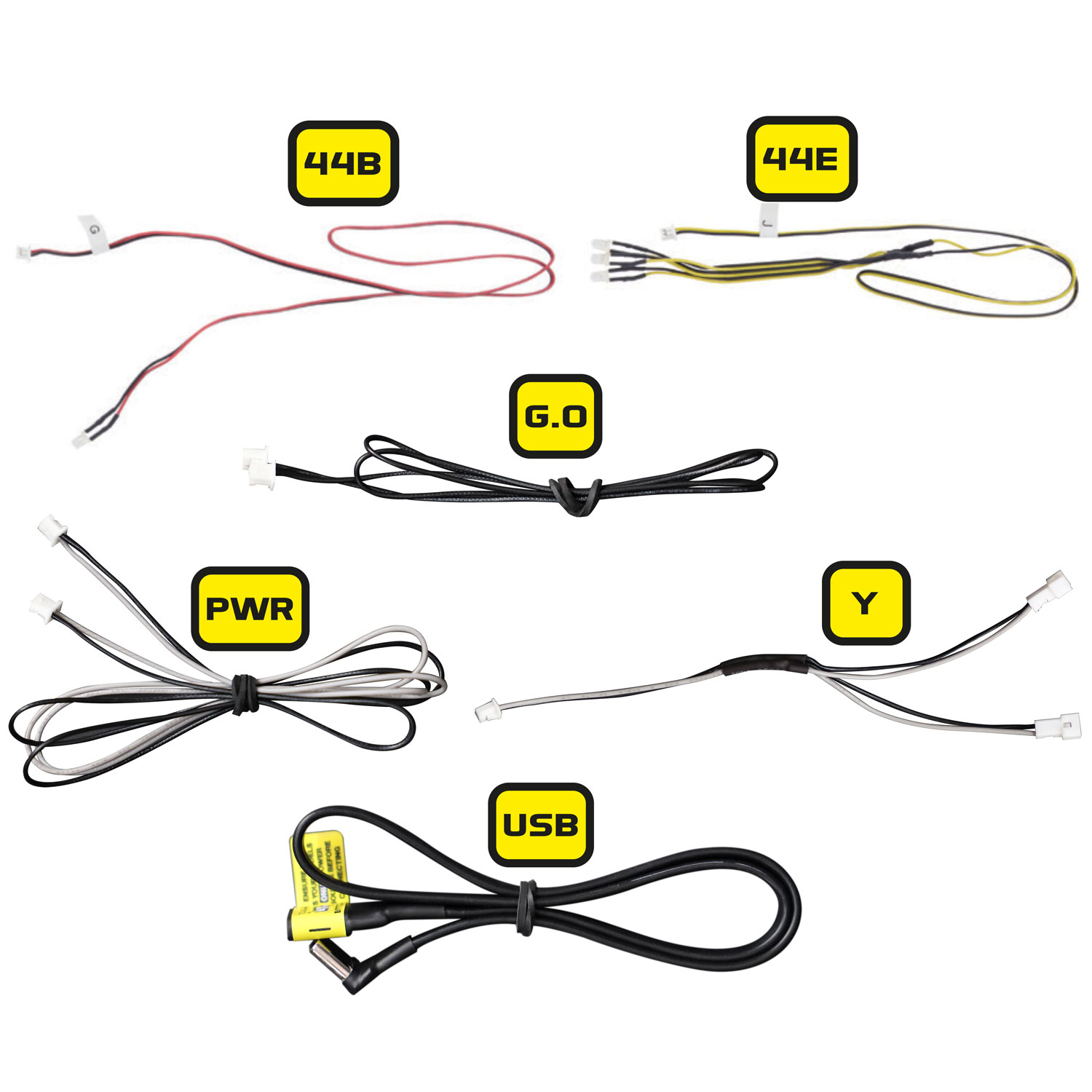
  • The 3 x LED’s that feed into the lower dash – 44E (J) with the yellow cables and part 44B (G) with the red cable
  • The black G.O data cable that was supplied with the monitor kit
  • The black and grey PWR power cable that was supplied with the monitor kit
  • The black and grey Y-splitter cable that was supplied with the monitor kit
  • The USB power extension cable that was supplied with the monitor kit

None of these cables will be required again – communication and power to the monitors will be provided through a new 5-core cable supplied within the Ultimate Electronic Kit.

Remove lower dash panel by inserting screwdriver

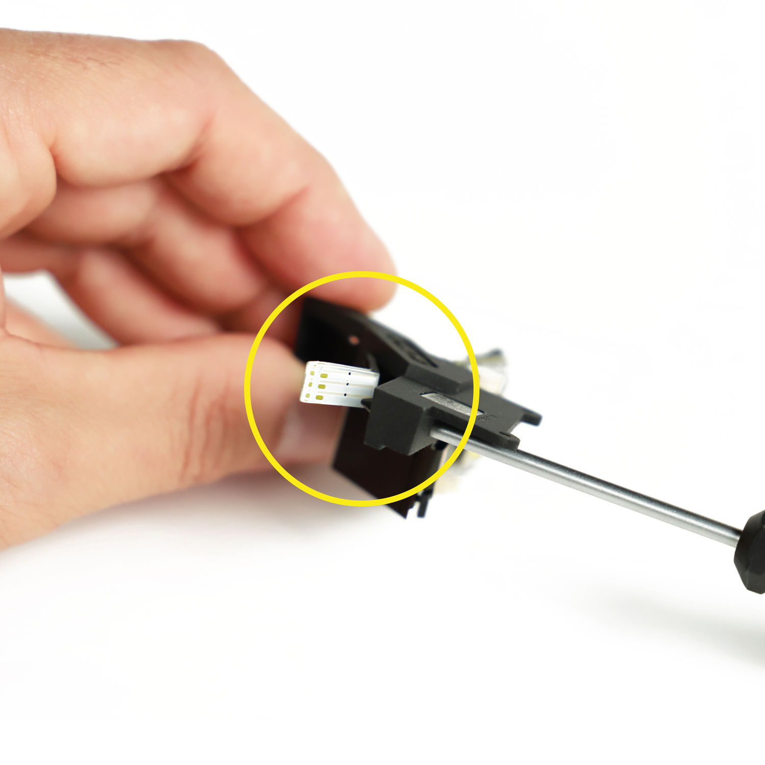
Once all the cables have been removed, you can also remove the lower dash panel by inserting a screwdriver through the LED holes and pushing from behind the panel. A PH0 Wera screwdriver for example fits perfectly.

The dashboard housing is now ready to take the electronic dashboard and upgraded panels.

Preparing the Mike Lane dashboard monitors

Preparing the Mike Lane dashboard monitors

If you purchased your Mike Lane Dashboard Monitors separately before June 2024, then you will need to perform a firmware upgrade on them to ensure compatibility with the Alpha Circuit Pro and to make use of the exciting new capabilities.

If you purchased the Mike Lane Dashboard Monitors together with the Ultimate Electronic Kit, then you can skip this step – they will already be installed with the latest firmware and no update is required.

Any monitors purchased after this date will be fully compatible with the Alpha Circuit Pro out of the box, but may still benefit from updates in the future when newer firmware versions are released.

This is a critical step, it only takes 2 minutes and must be performed before continuing with the installation.

  Firmware upgrade instructions

For detailed instructions on how to carry out an upgrade, please follow this link: https://mikelanemods.com/kitt-dashboard-monitors-firmware-update/

Preparing the rear side markers

Preparing the rear side markers

Removing rear left reflector (101A)
The Ultimate Electronic Kit includes two sets of side marker LED’s, red for the rear of the car and amber for the front. These are to be installed into the existing enclosures.
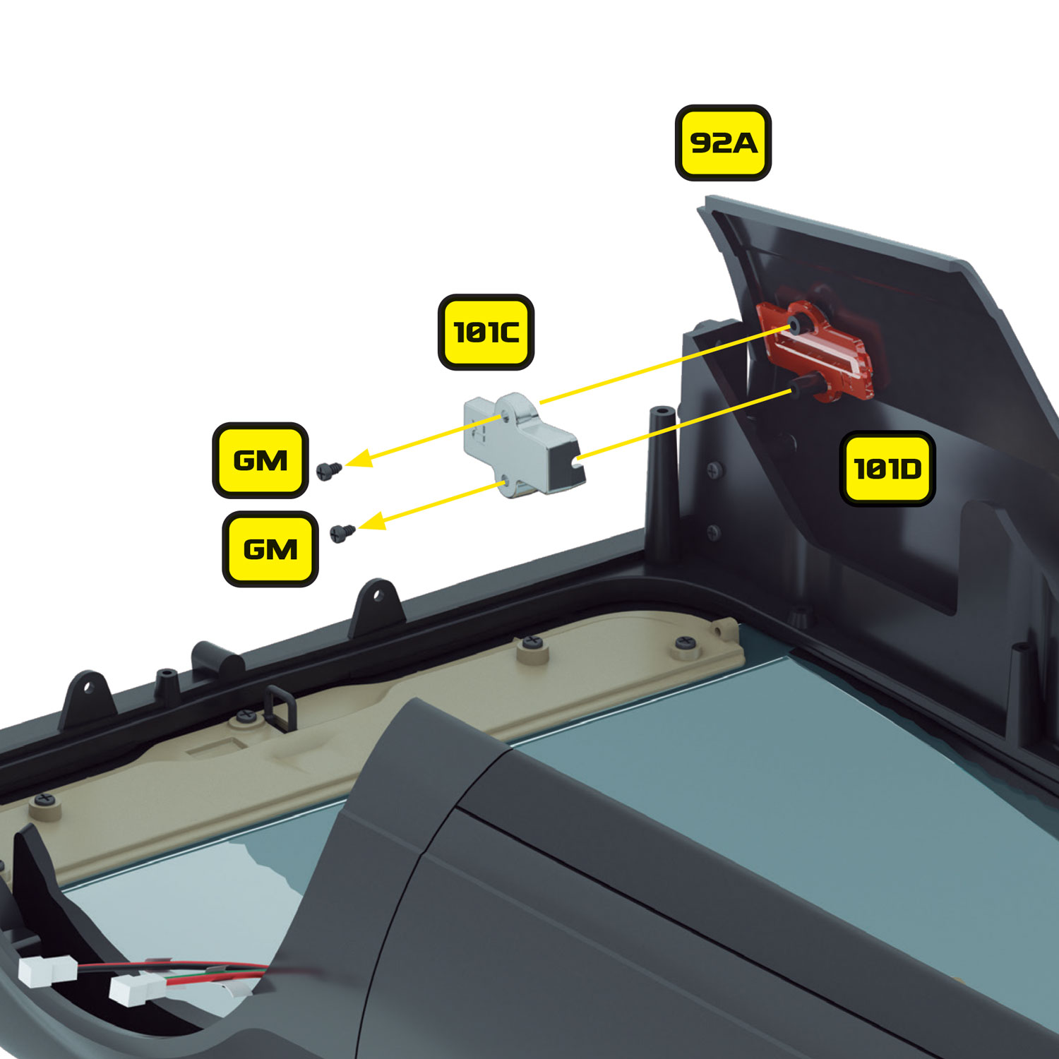
Removing rear right reflector (101C)

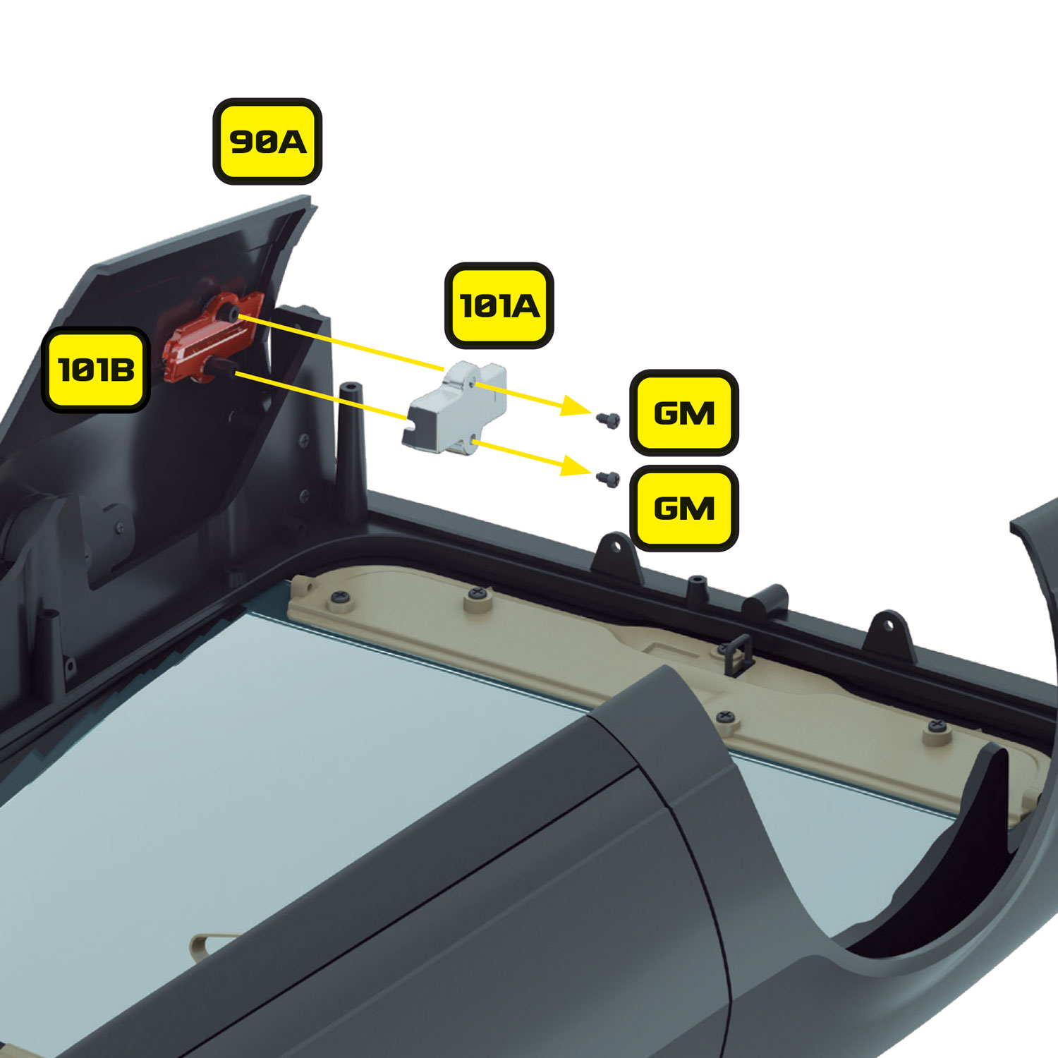
The rear marker lenses were originally installed in Stage 101. Start by removing the rear reflectors on the left (101A) and right (101C) of the car, each is held in place with 2 x GM screws.

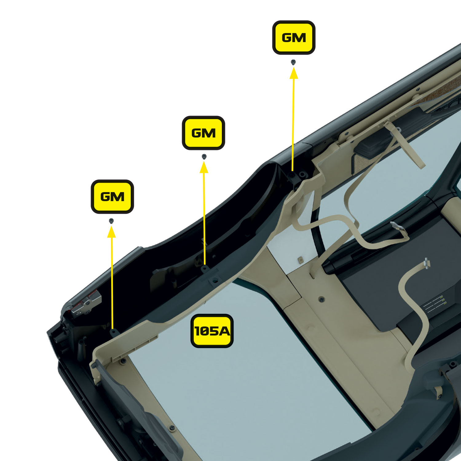
Removing rear trunk panels and the rear trunk wall

If you have already installed the rear trunk panels (102A and 105A) and the rear trunk wall (104A), you will need to remove these to gain access to the rear marker enclosures. Refer to Stages 102, 104 and 106 for details or removal and refitting.

The rear wings are now ready to take the side marker LED’s.

Preparing the front side markers

Preparing the front side markers

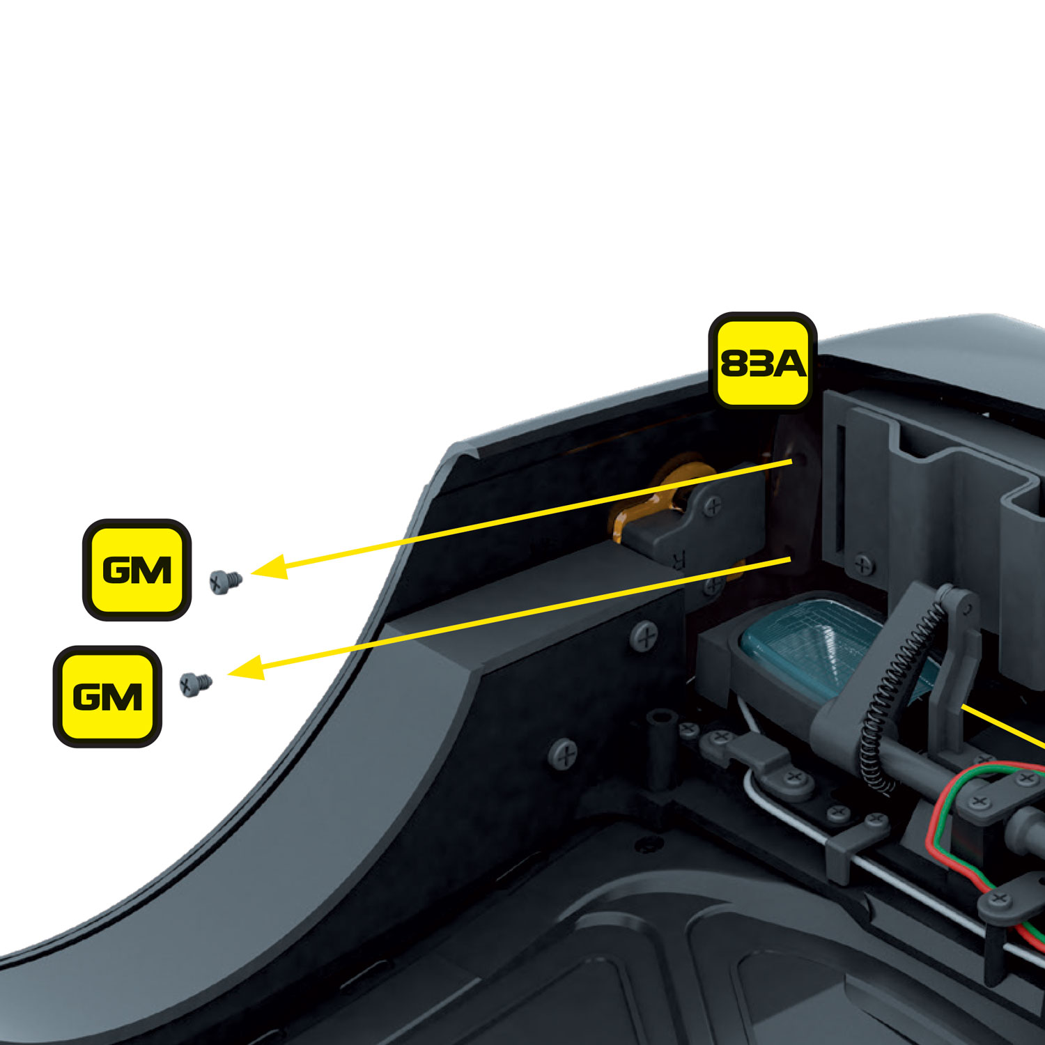
Removing screws connecting the front of wing to back of front bumper
The front marker lenses were installed in stages 83 and 85.

To gain access the wing, and also prepare the bumper for installation of the scanner, we will first need to remove 2 x GM screws that connect the front of the wing to the back of the front bumper.

Then, remove the remaining GM screw that holds the front bumper onto the body. Put the front bumper safely to one side for preparation of installing the new scanner.

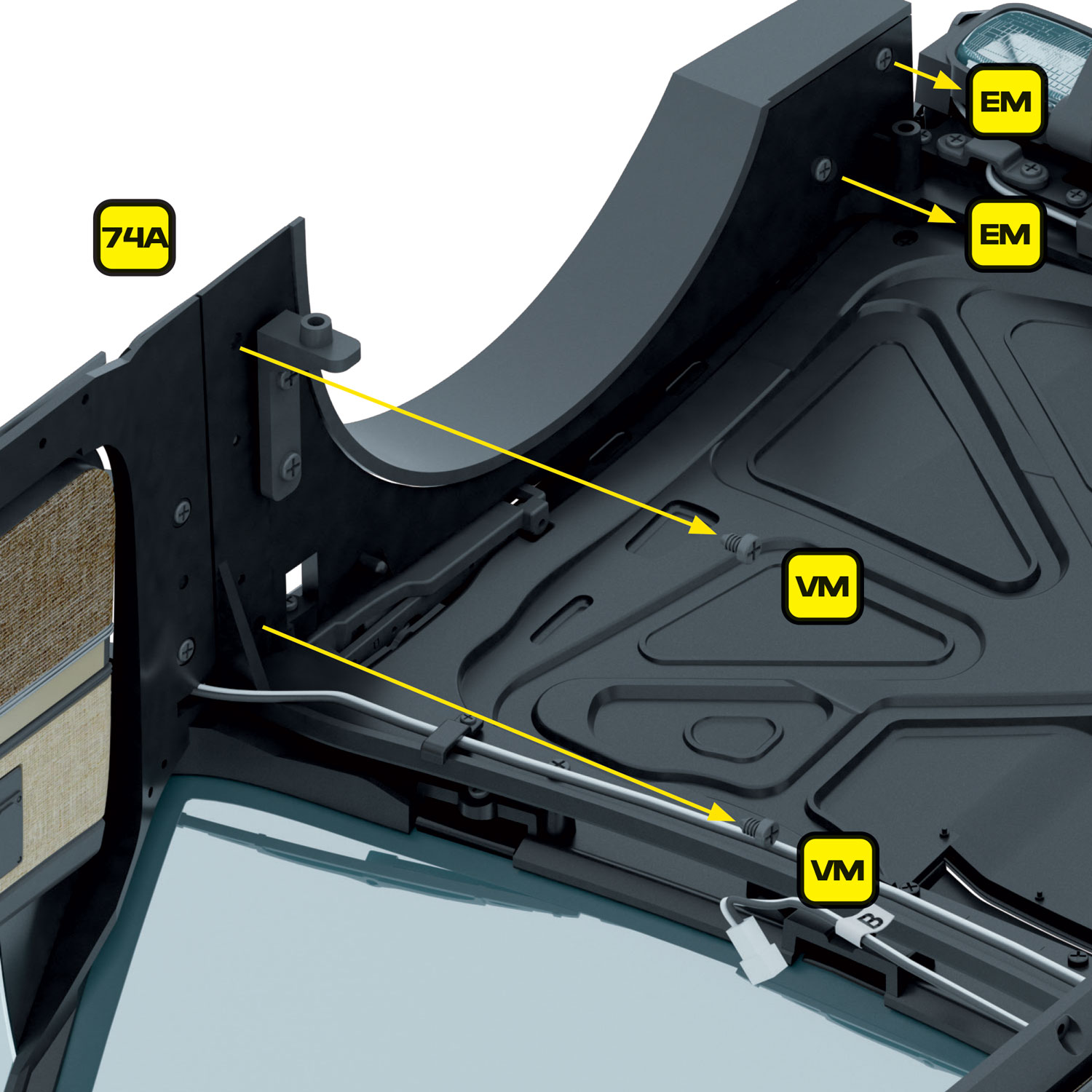
Then, remove the front right wing by unscrewing the 2 x EM screws at the front and the 2 x VM screws on the rear as shown.

Removing screws that hold lens reflector in place

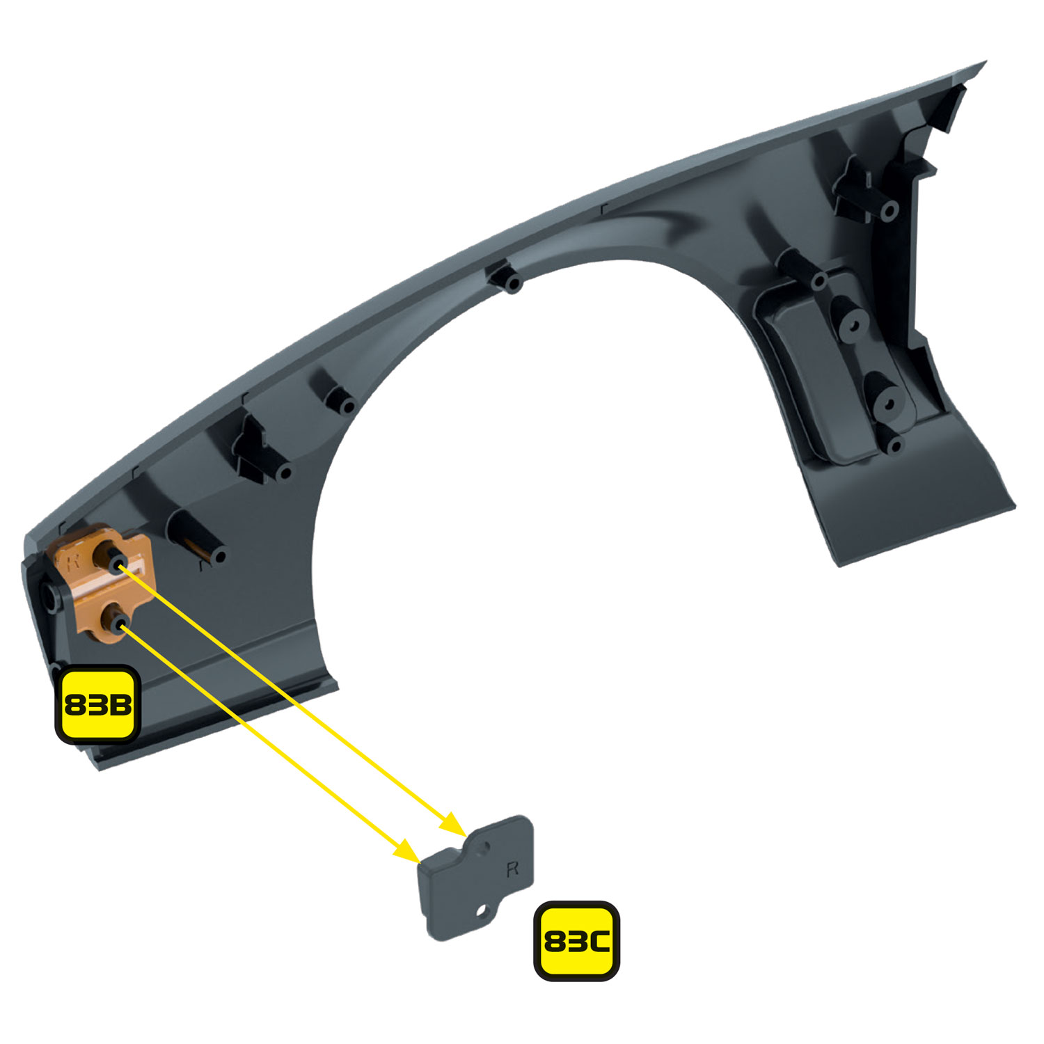
Remove the 2 x EM screws that hold the lens reflector (83C) in place.

Repeat the wing and lens reflector removal process on the other side of the car.

The front wings are now ready to take the side marker LED’s.

Preparing the front bumper for the new scanner

Preparing the front bumper for the new scanner

Removing screws connecting the front of wing to back of front bumper
The scanner is designed to replace the stock scanner and mount to the original bracket.

If you have completed Stage 86, and if you haven’t already done so in the previous step, remove the 2 x GM screws on each side that connect the front bumper to the front wings.

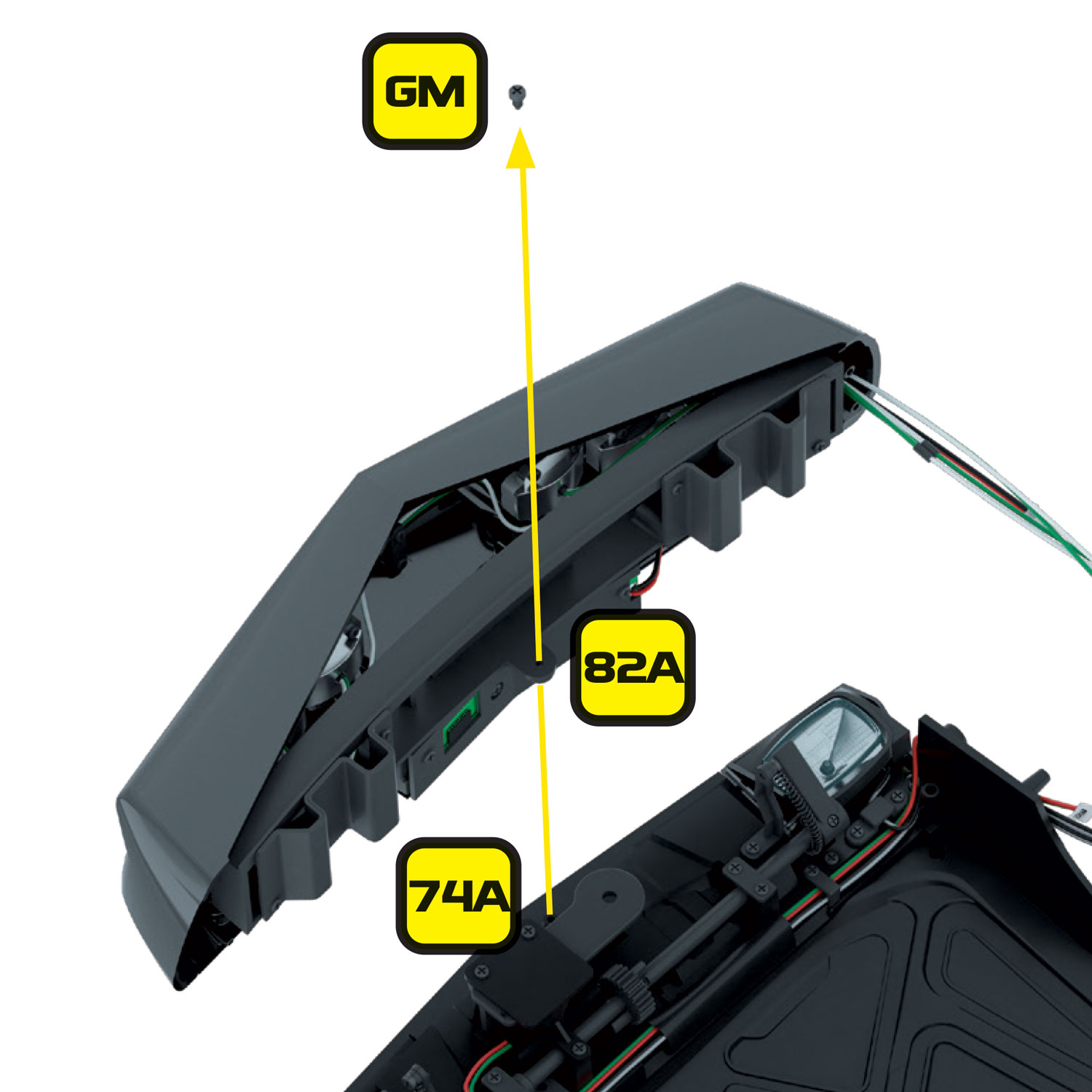
Then remove the 1 x GM screw from the centre of the front bumper that connects to the front engine bay frame (74A).

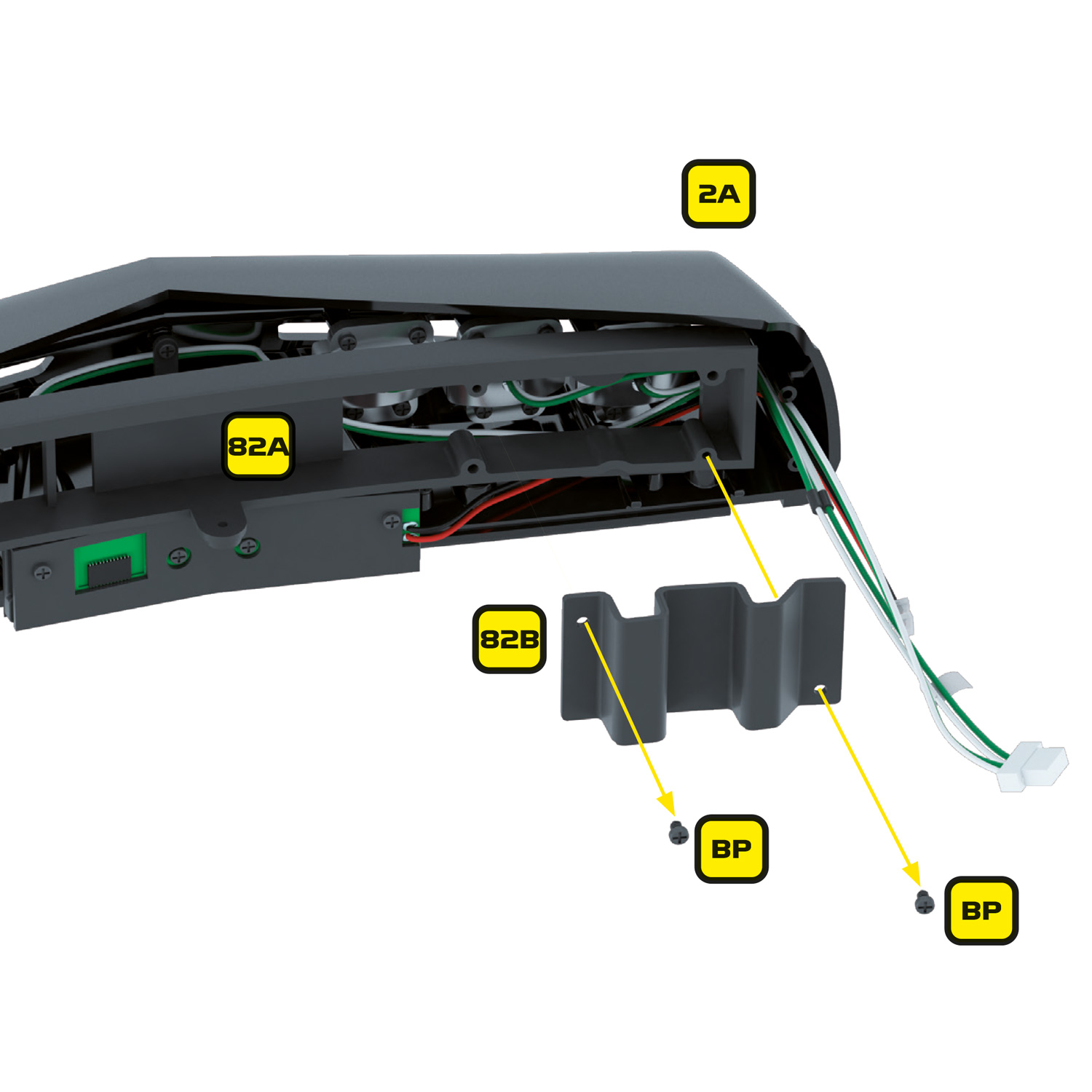
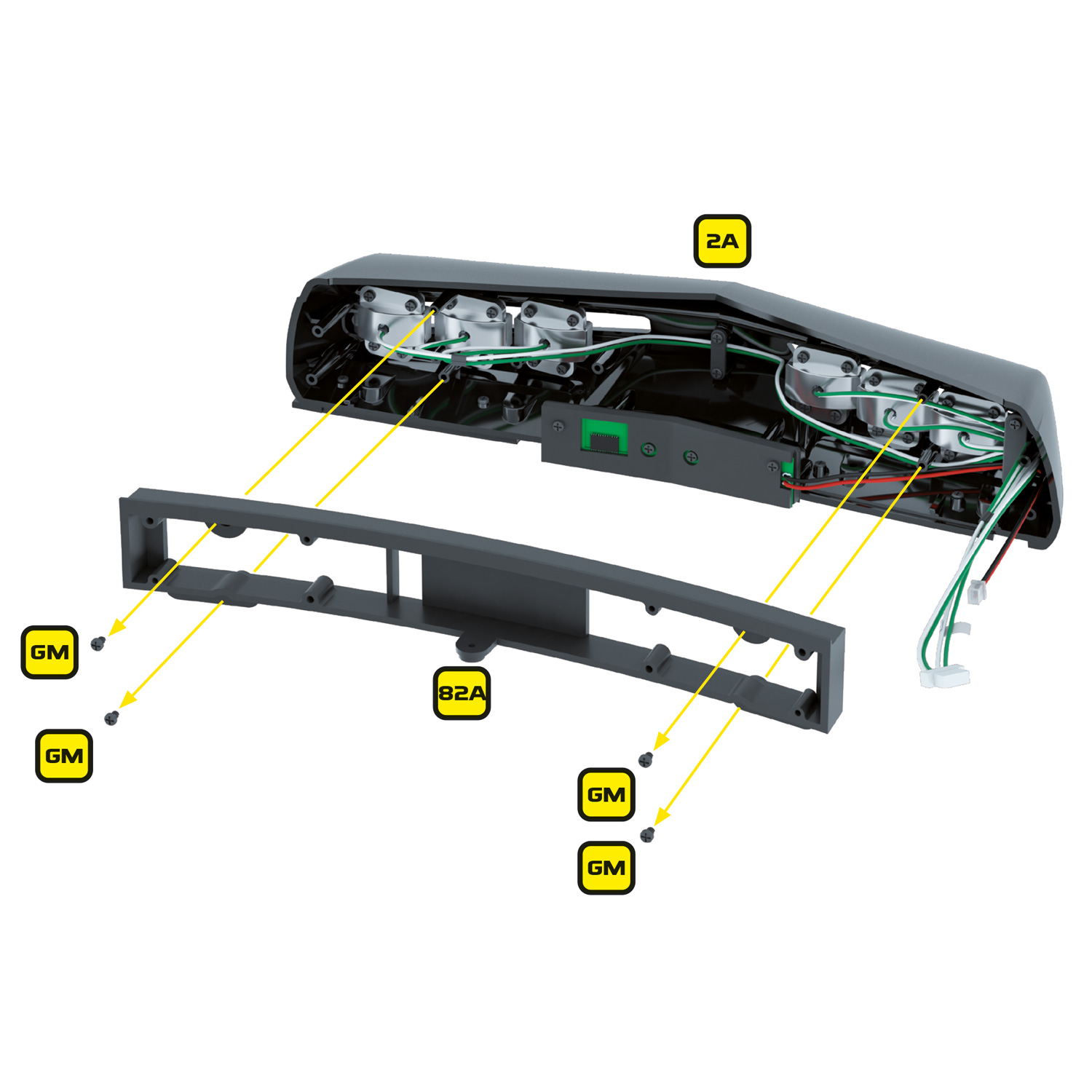
If you have already completed Stage 82, you will need to remove the left and right bumper brackets (82B) and (82C).

Next remove the inner frame (82A). Set these parts and their associated screws aside for refitting later.

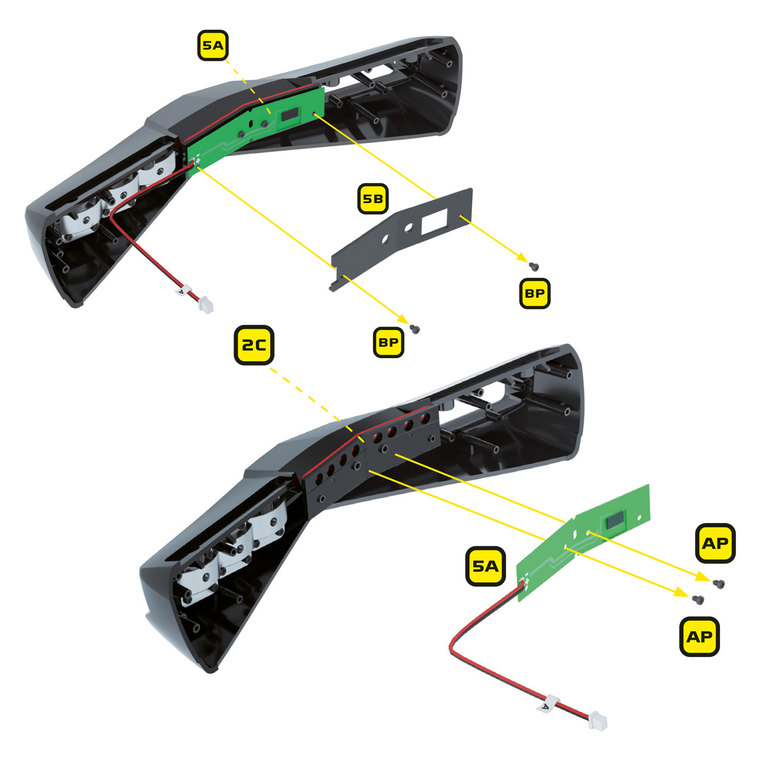
Remove the 2 x BP screws holding the inner case of the scanner (5B) in place. Next remove the stock scanner circuit board by removing the 2 x AP screws holding it in place. Except for the scanner which will no longer be needed, keep all of these parts and screws safe as they will be re-used for the Mike Lane scanner.

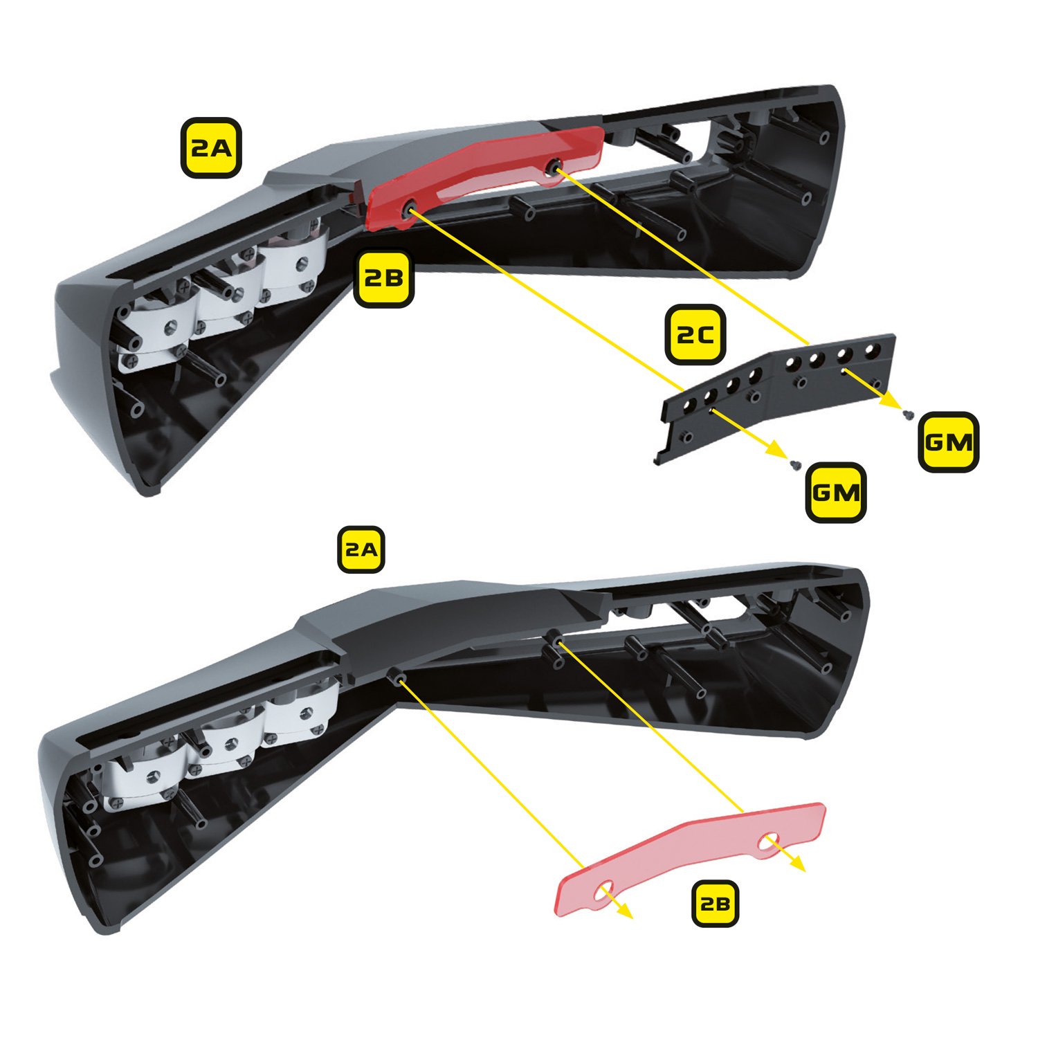
Remove the scanner base (2C) and scanner lens (2B) from the front bumper. The lens will no longer be required but the scanner base will be re-used.

The front bumper is now ready to take the new Mike Lane scanner.

Preparing the tail lights

Preparing the tail lights

To install the additional tail lights and reversing lights, you will need to remove the tail light base installed in stage 98 and drill 4 x 3mm holes in it for the new LEDs.

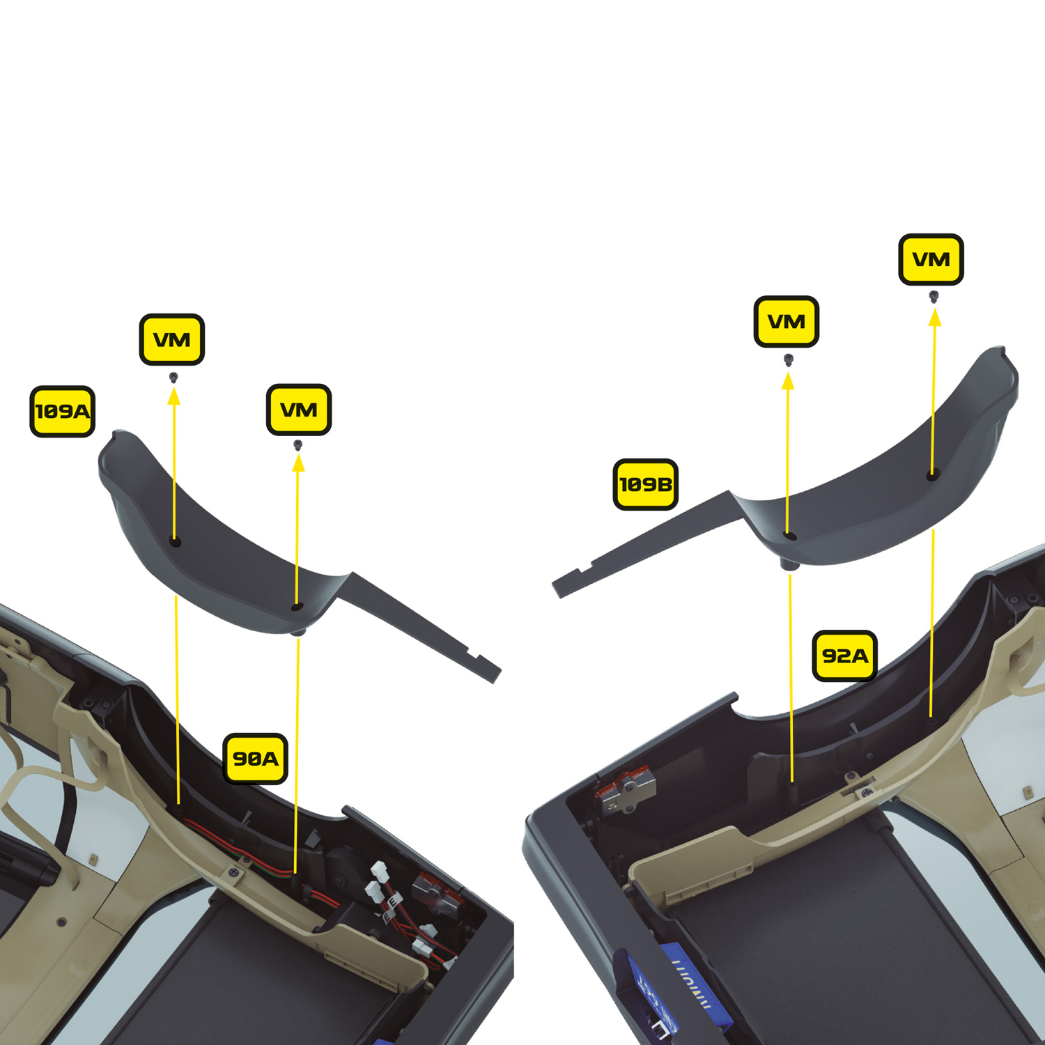
Start by removing the rear fenders (109A and 109B) installed in stage 109. These are held in place with 2 x VM screws on each fender. Keep these parts and their screws safely to one side.

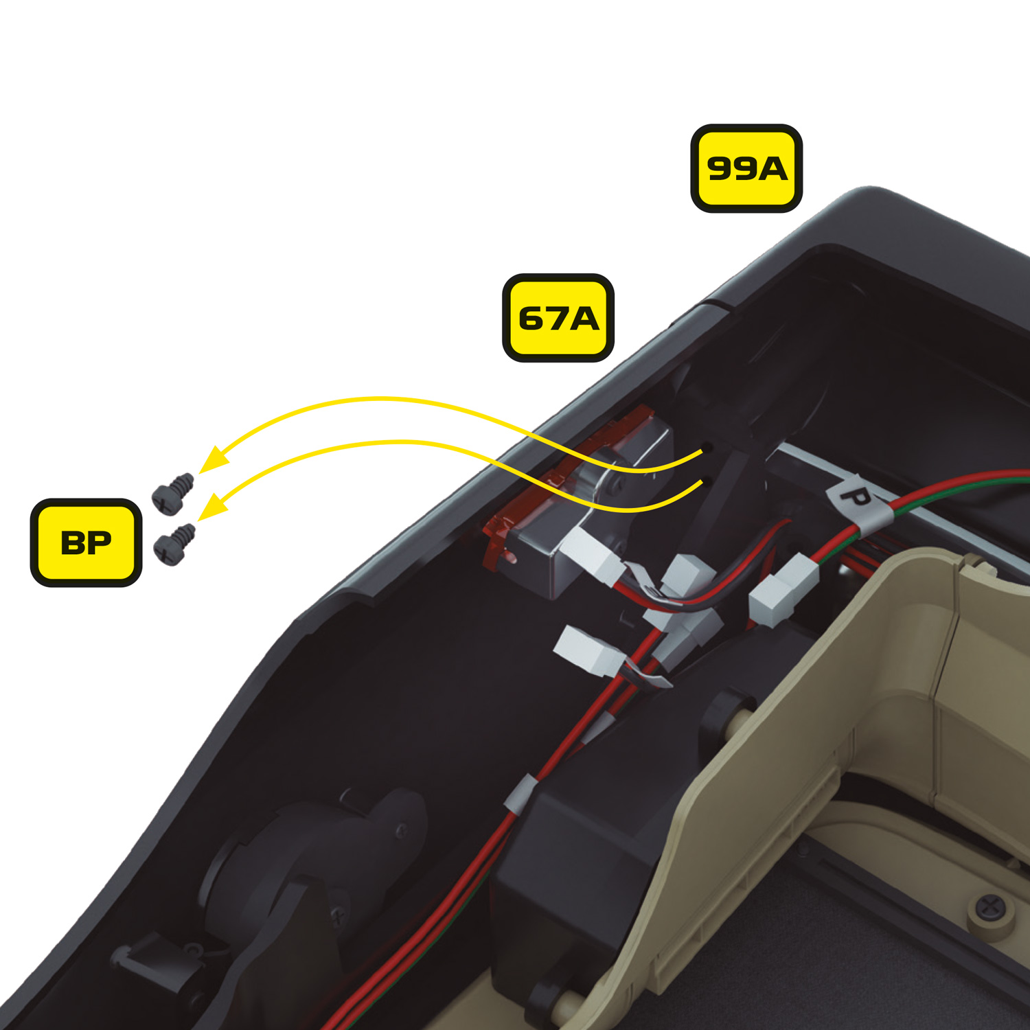
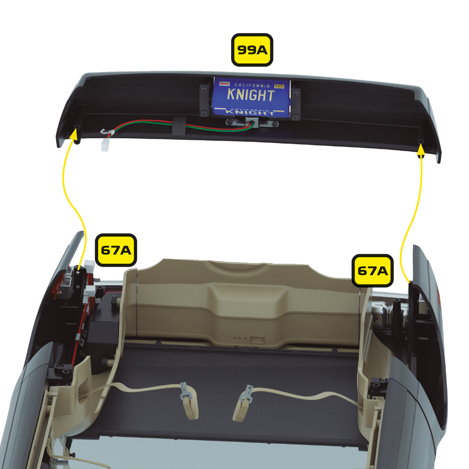
Remove the 4 x BP screws that hold the rear bumper in place.

Remove the rear bumper (99A).

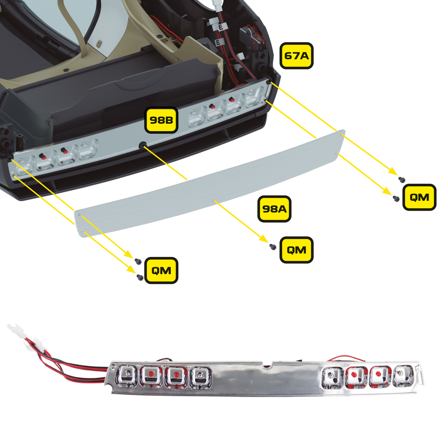
Remove the 5 x QM screws that secure the tail light cover (98A) and place it and the screws safely to one side.

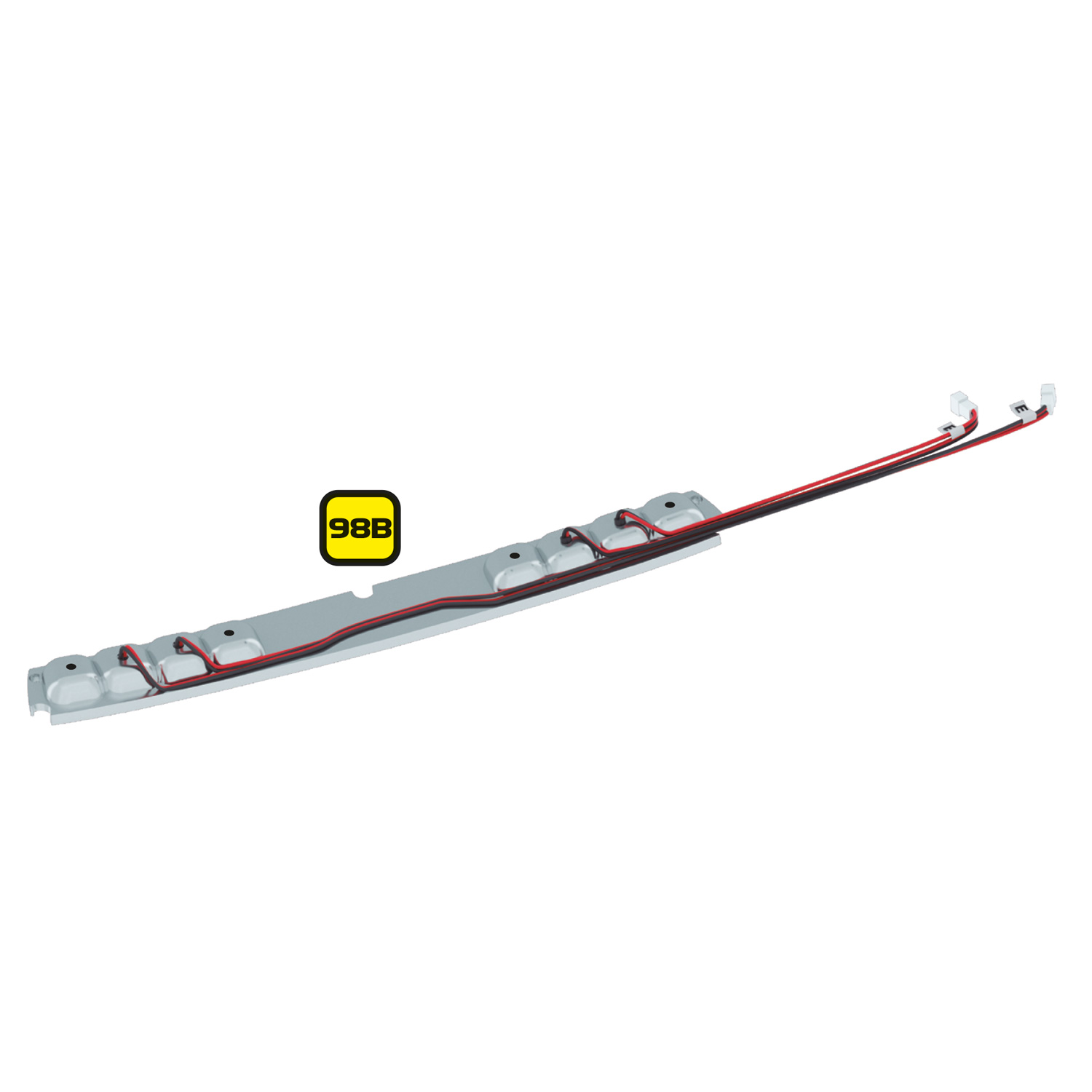
The taillight base (98B) should now slide up and out of place. Carefully remove the existing LEDs making note of their original locations.

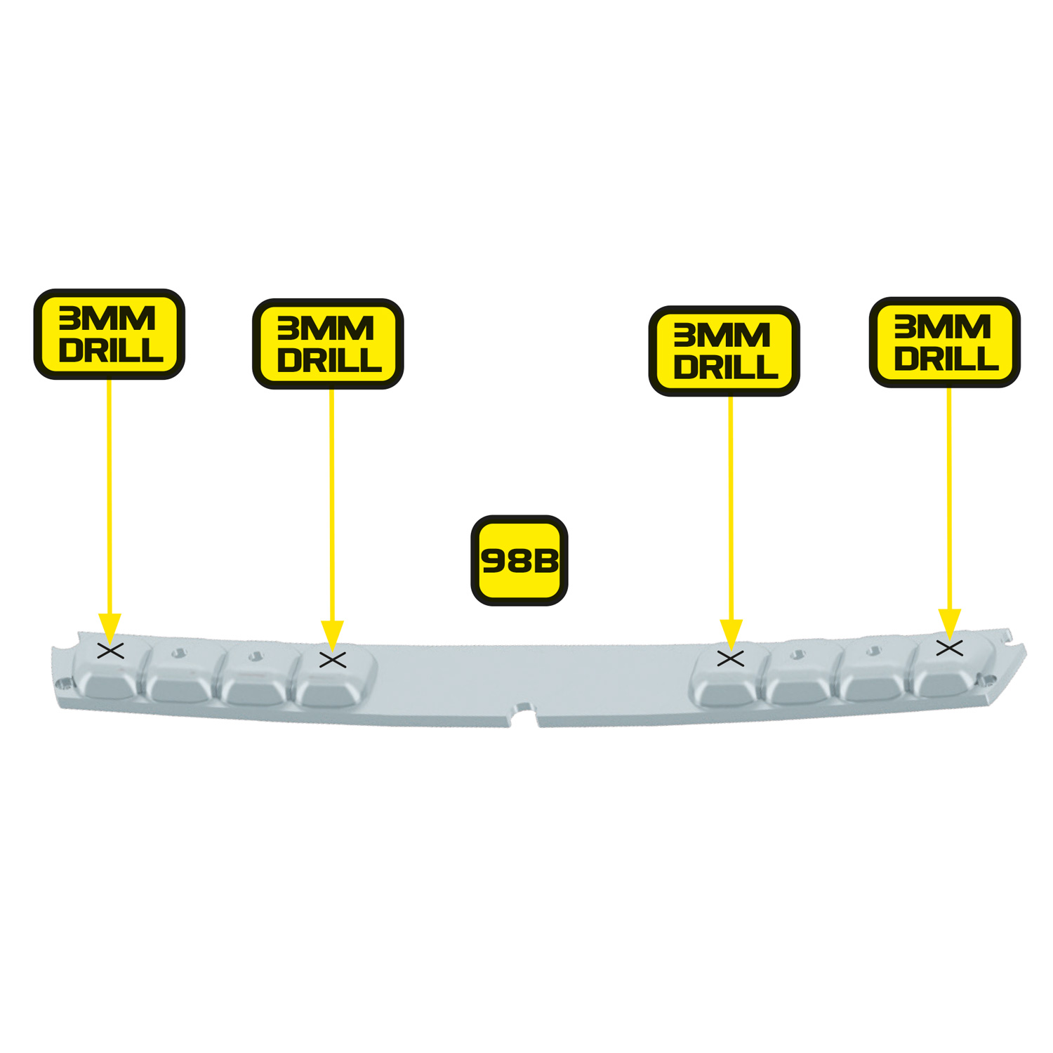
Next you will need to drill 4 new holes in the tail light base (98B), in each of the unused lamp positions. Place the base face down on a soft surface to prevent scratching and carefully mark the centre point of each lamp position. Then, using an appropriate hand drill, carefully drill a 1mm pilot hole in the centre of each lamp position, followed by a 3mm hole.

Once complete, you can reinstall the original LEDs in their original positions. It is important that the original LEDs go back on the correct holes as they also serve as brake lights.
The taillight base is now ready to take the new reversing and brake LEDs.

You are now ready to install the Ultimate Electronic Kit

Ultimate Electronic Kit for 1:8 KITT model from Mike Lane Mods