Step 1 Assembling the Roof Box
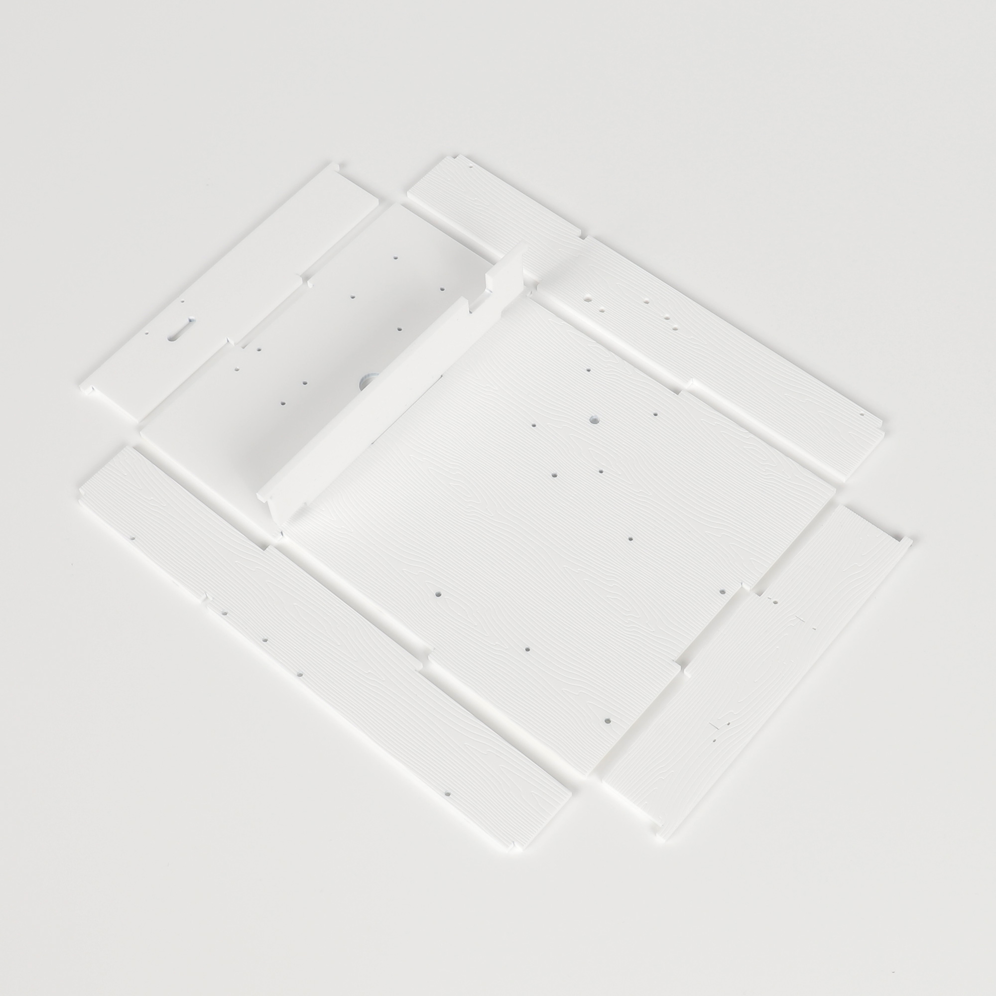
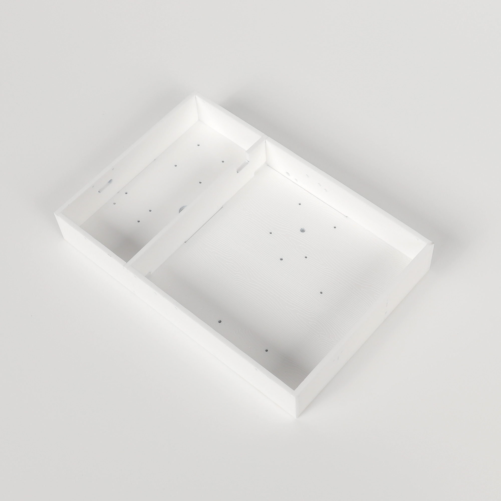
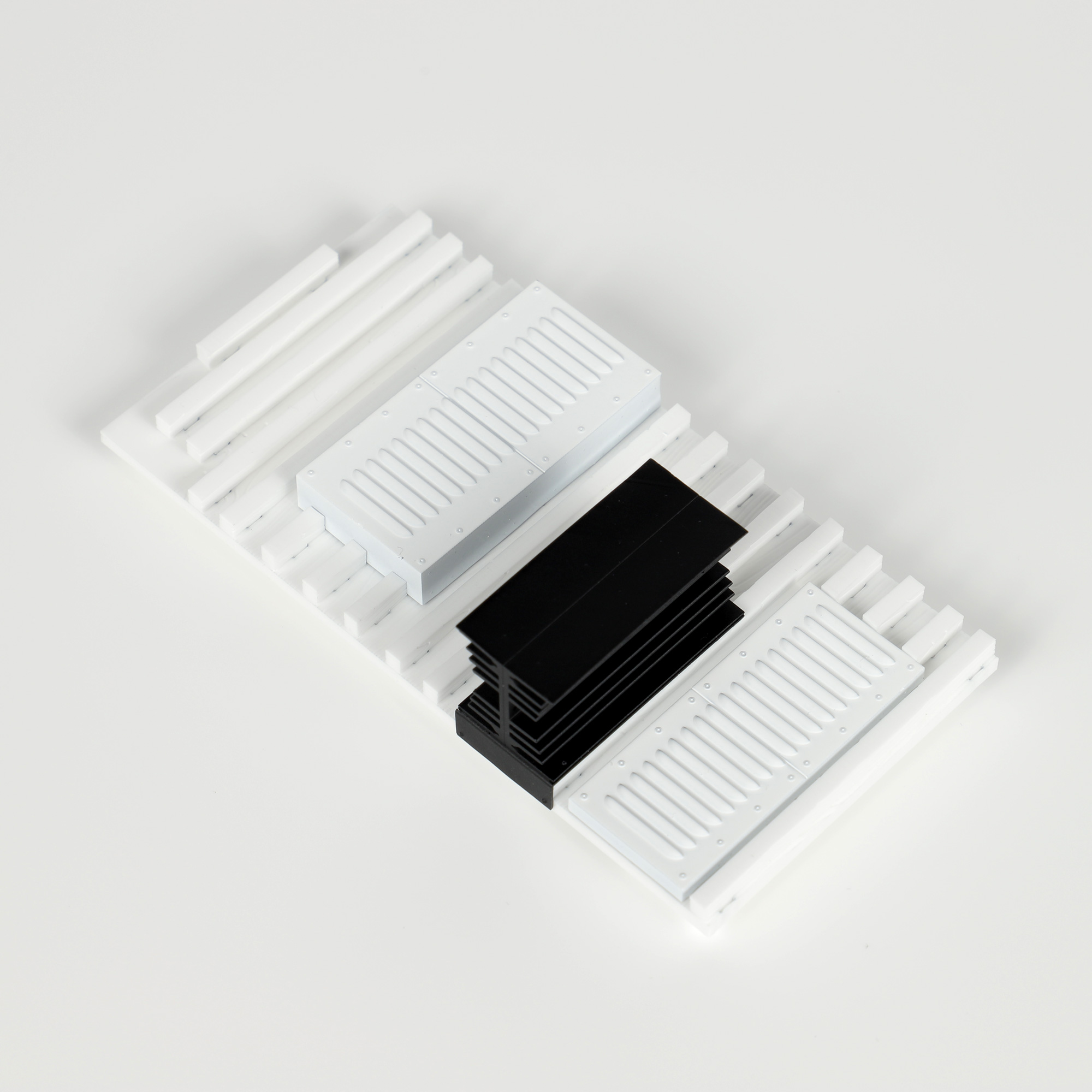
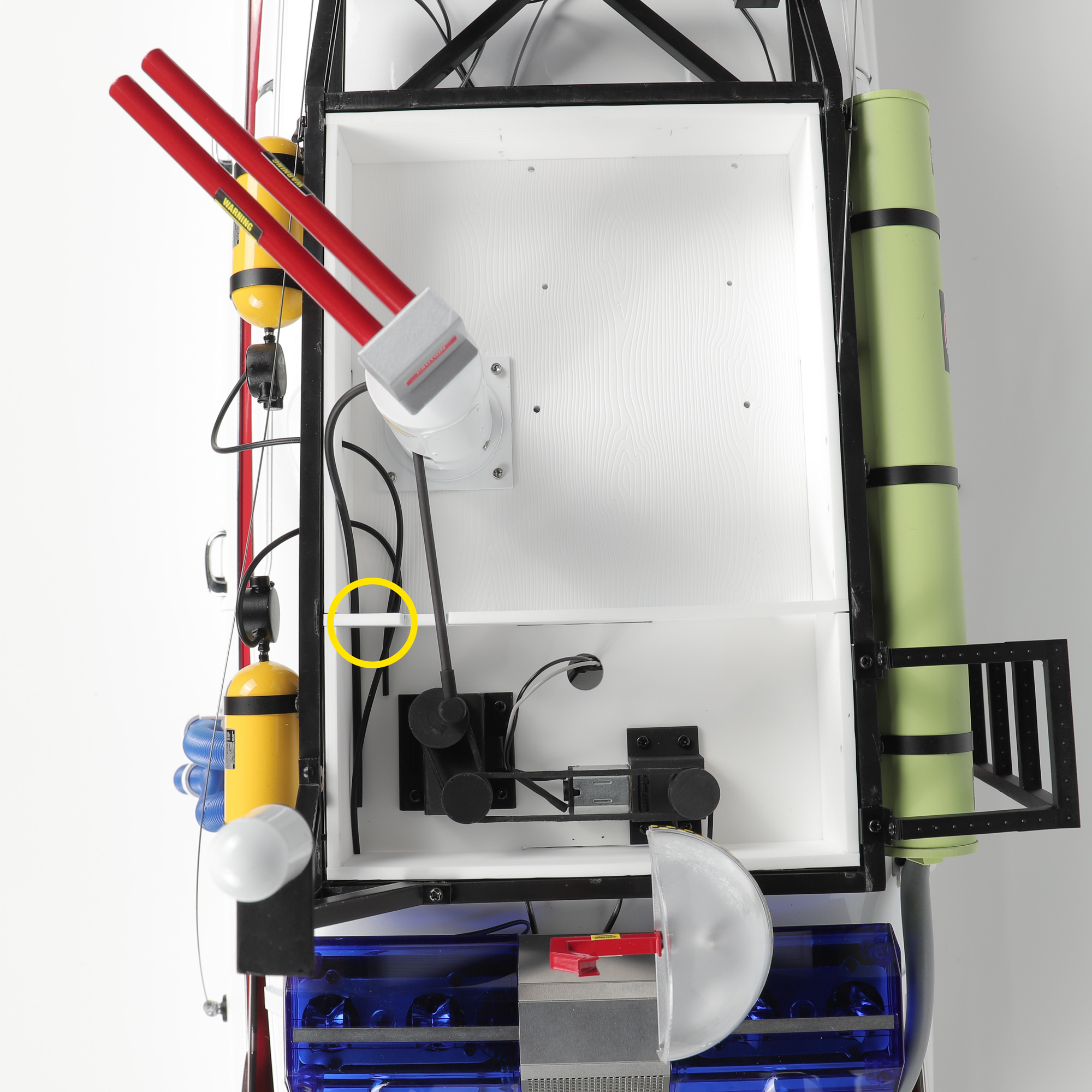
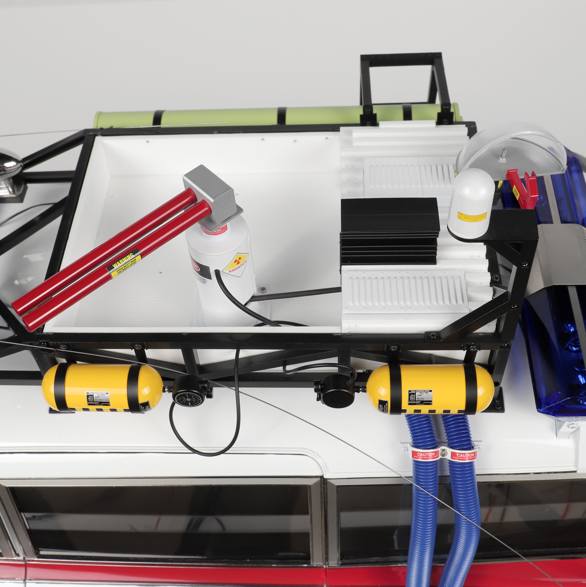
- Begin by loosely constructing the roof box, ensuring all the pieces are in the correct place and orientation matching the photo above. Note: Every side is unique, so correct placement is critical before gluing.
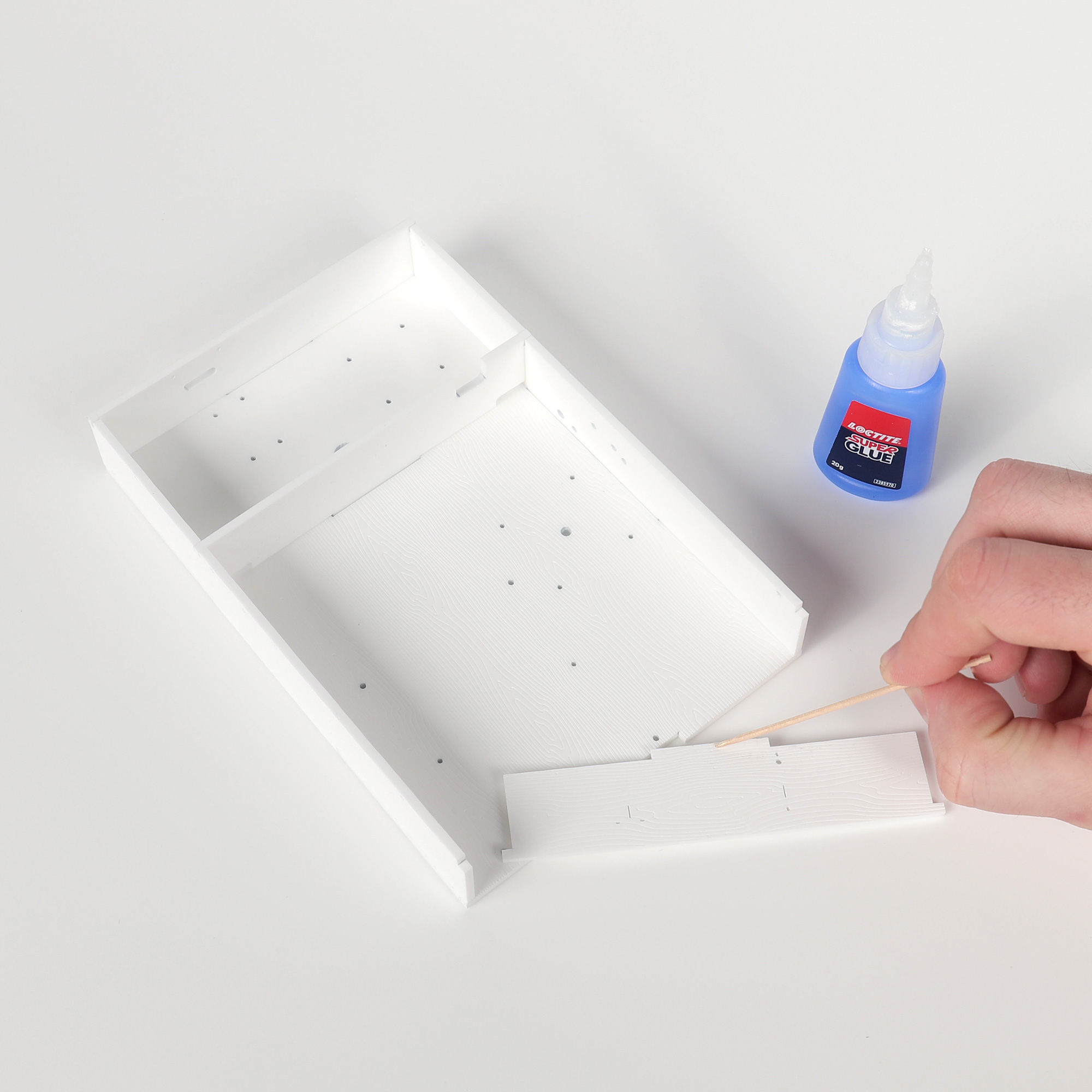
- Place a small dot of glue in each corner beneath the top tabs, and on the rear of the bottom tabs where the joint will be hidden. Be careful not to glue your box to your workbench during this process. Only a very small amount of glue is required – using less will reduce the risk of making a mess and any mistakes.
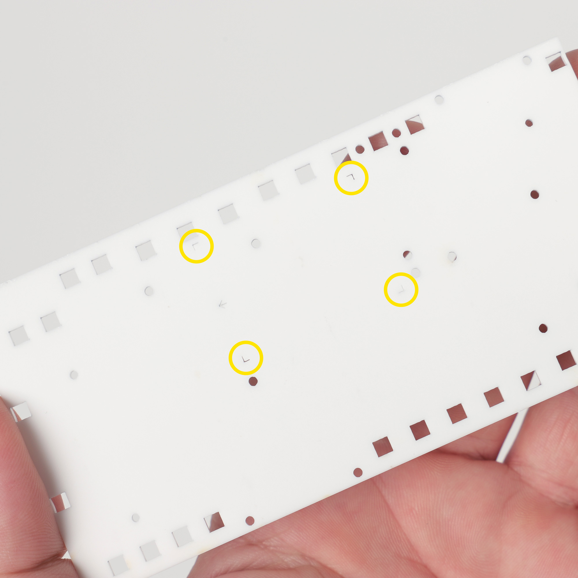
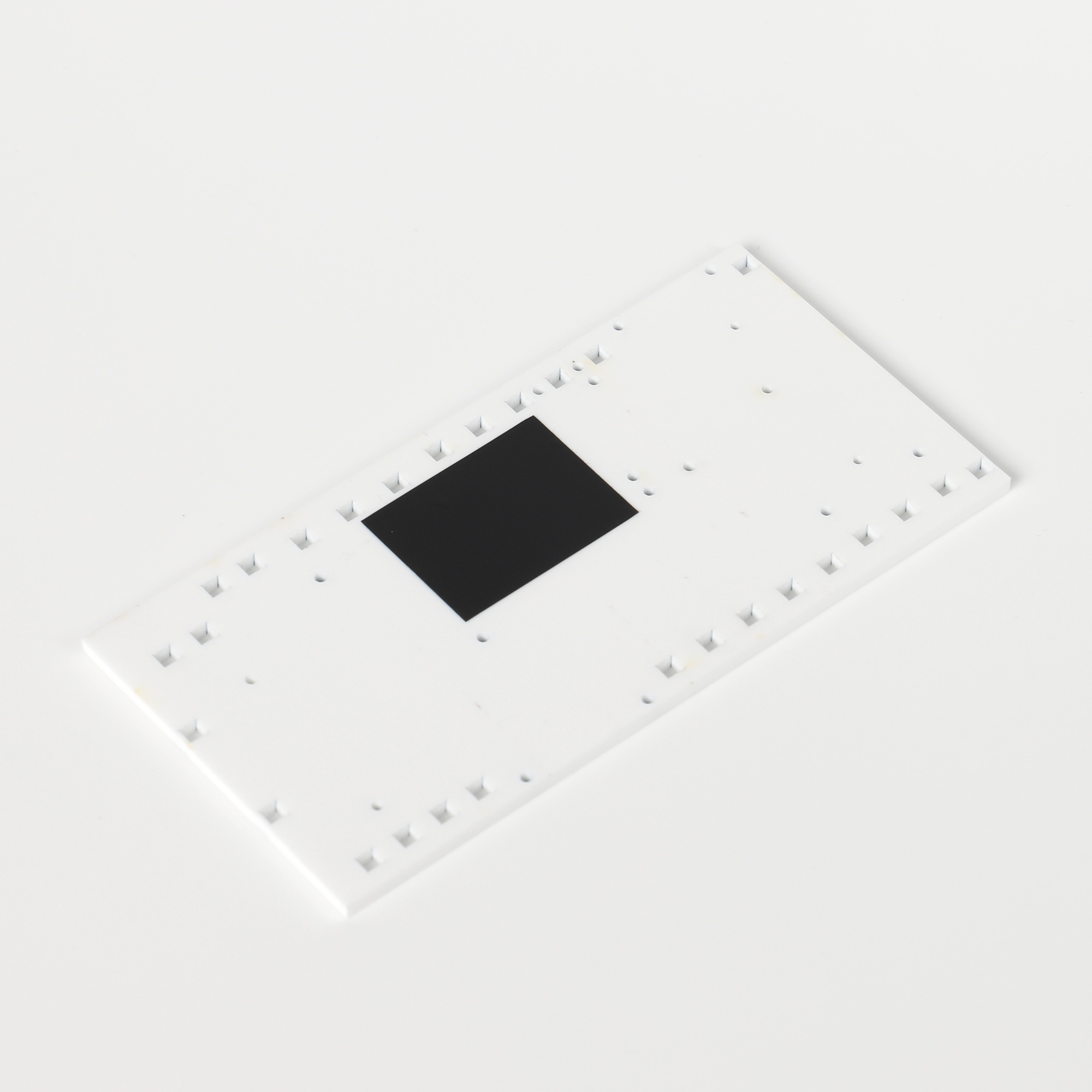
- Take the black rectangular piece of self-adhesive vinyl provided, and stick in to the marked position on the underside of the roof box lid (the side without the wood grain).
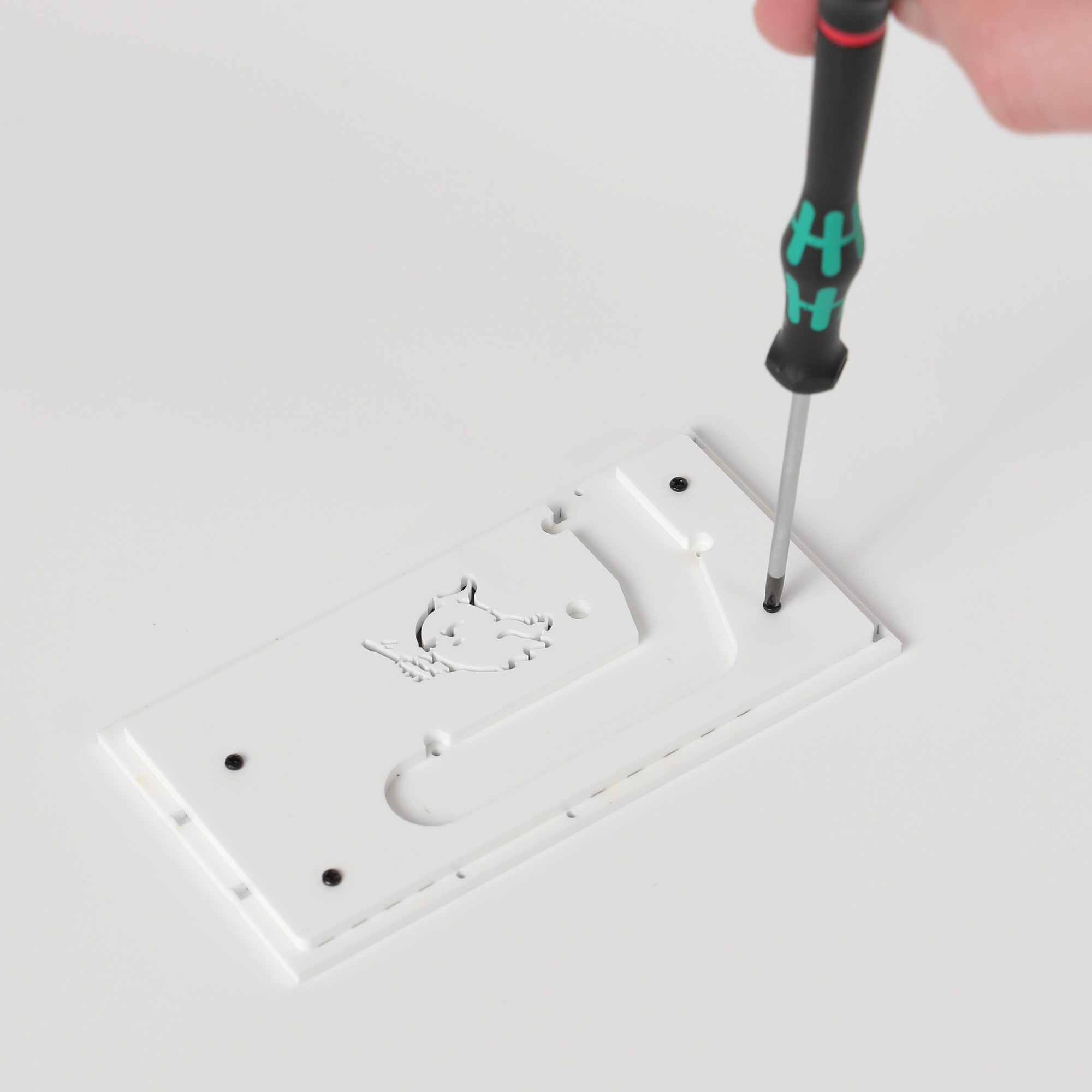
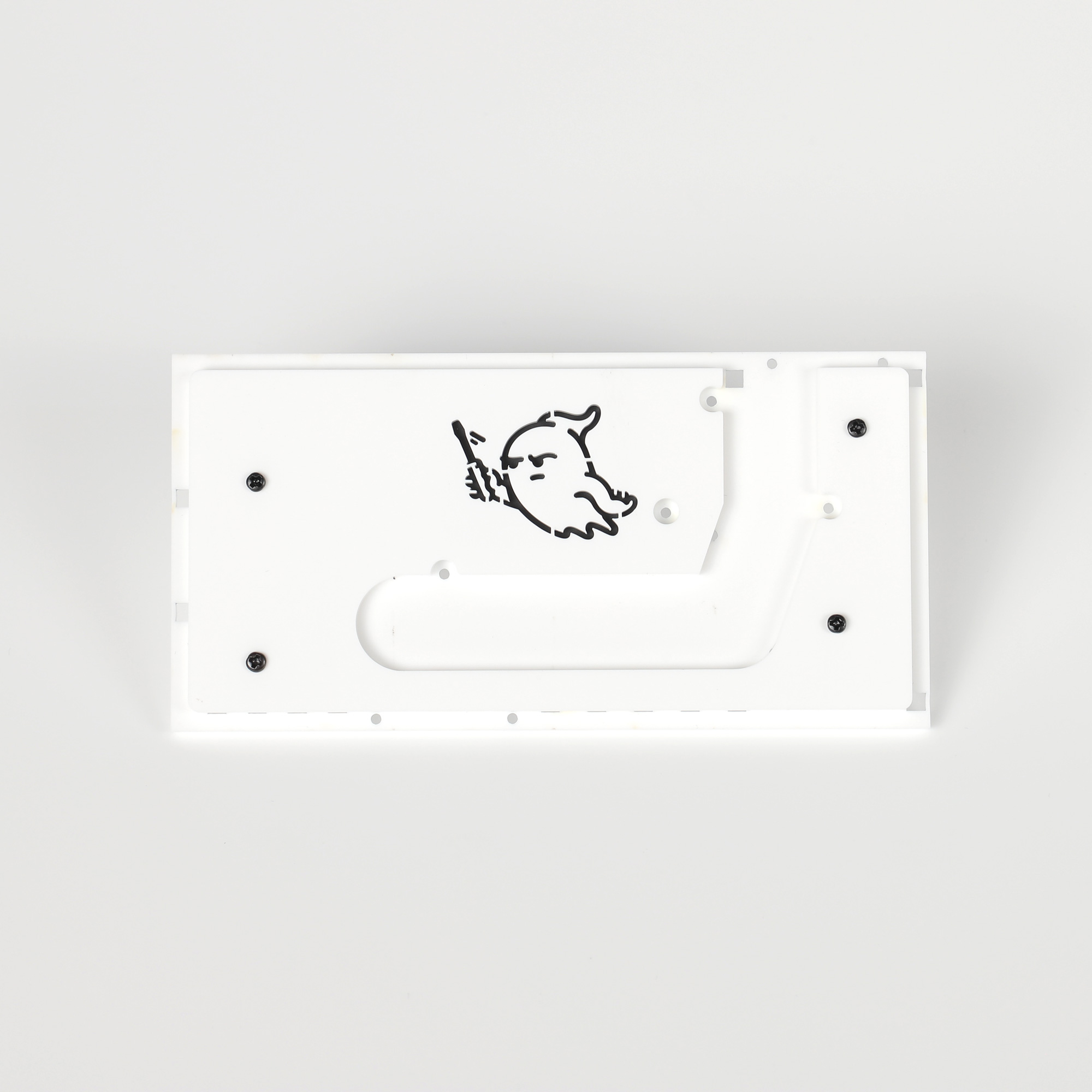
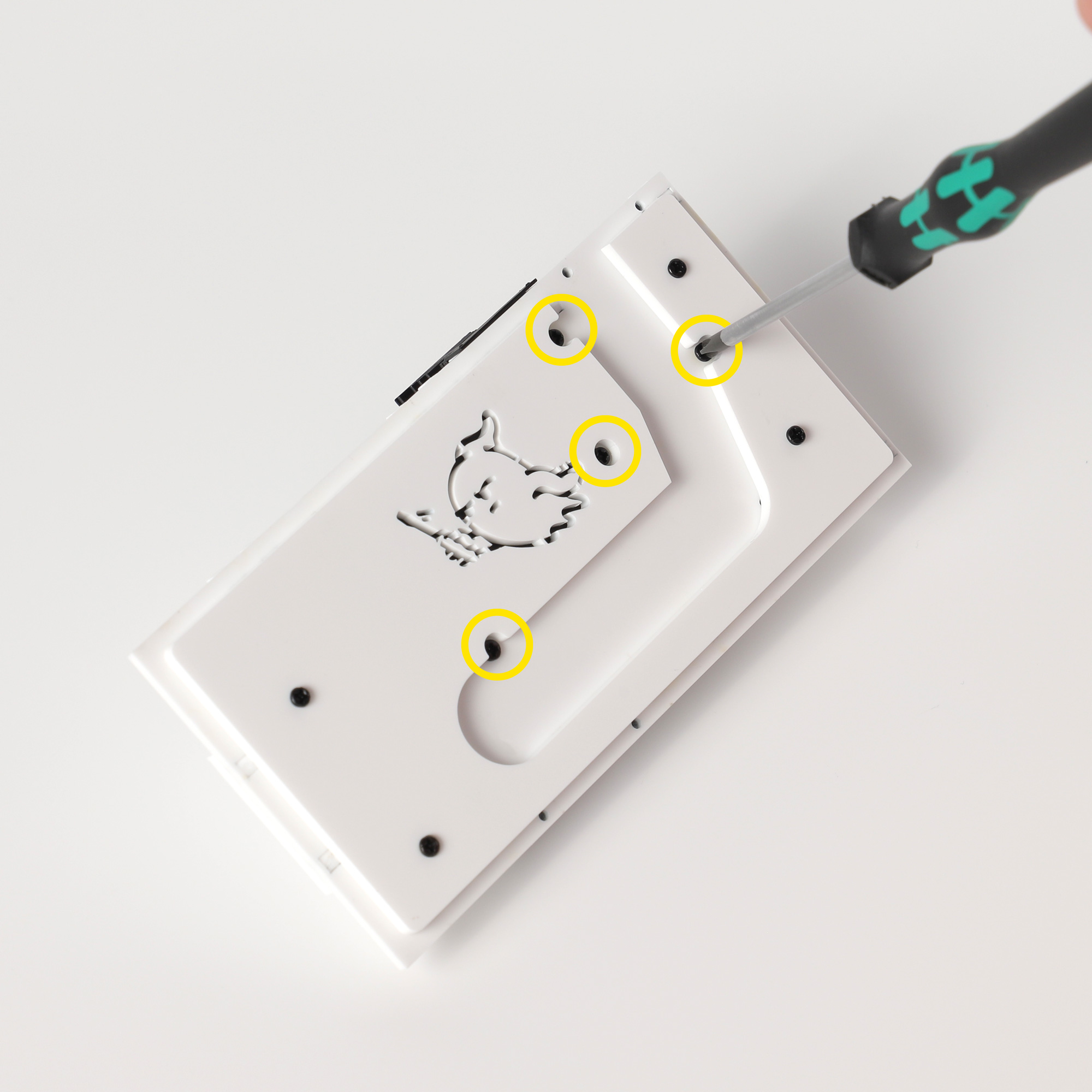
- Using a PH0 screwdriver, take 4 x ML5 screws and fit the roof box lid insert to the underside of the roof box lid, with the Ghost (‘Super Boo’ as we like to call him) pointing left.
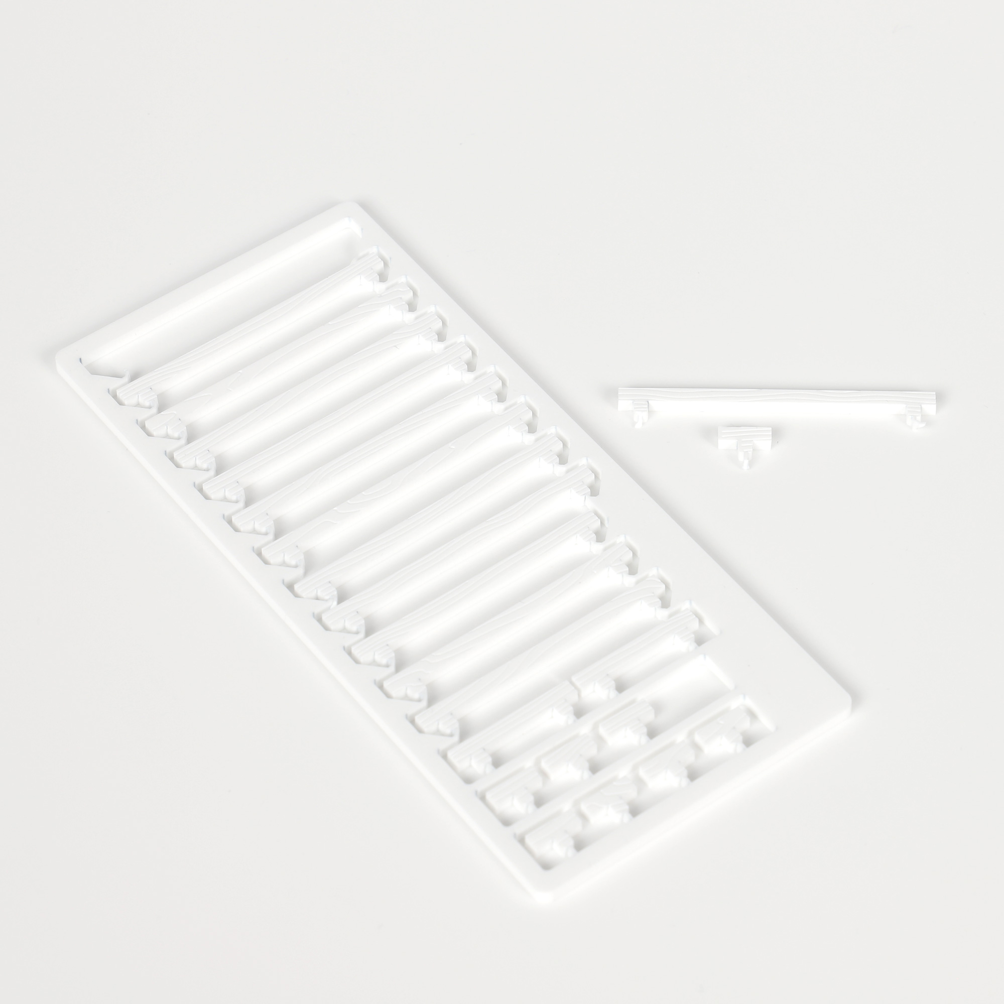
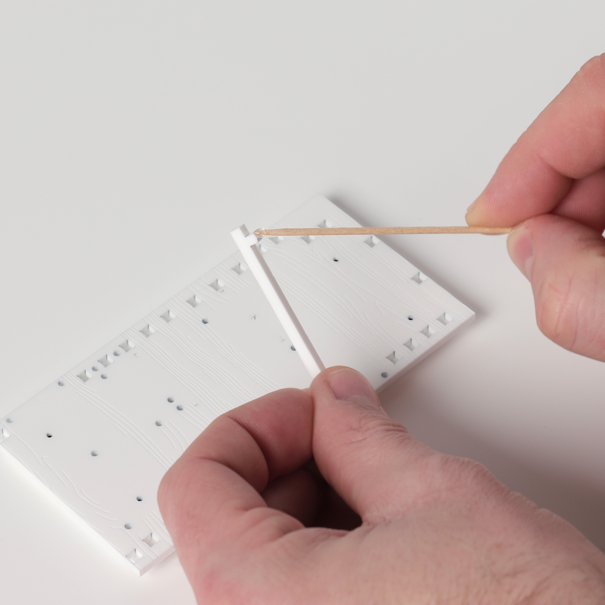
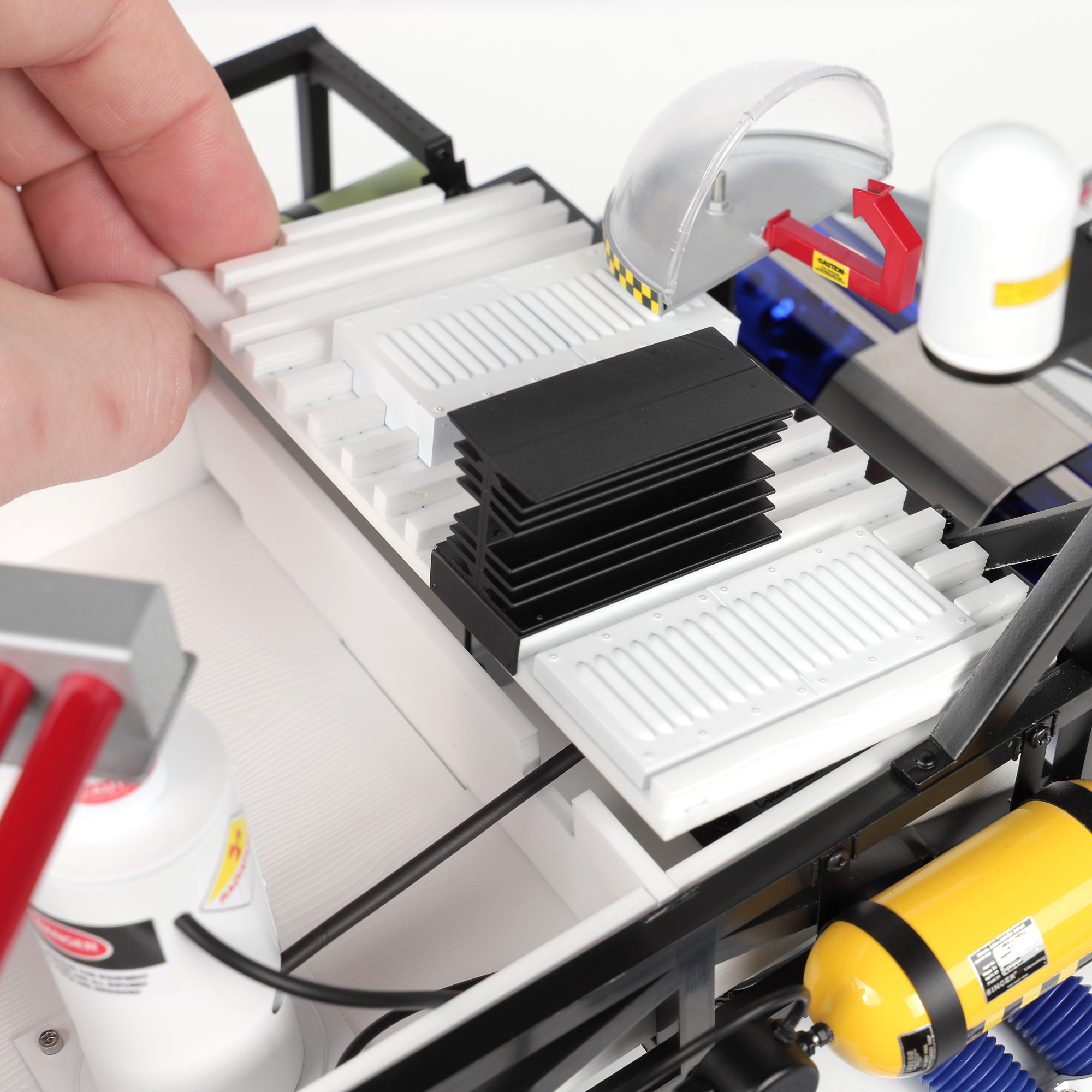
- Carefully break the roof box fins away from their supports – they will break away using your fingers. Then, using a good pair of scissors or a craft knife, trim off any spurs left on the fin tabs so that the bottoms are tidy and flush.
- Test fit each roof box fin before gluing into place. If any of the parts are too tight, don’t force them as they could break. Simply take a craft knife and shave a tiny amount off the side of each tab for an easier fit. Using a small drop of Loctite Super Glue on each tab, start fitting the top fins along the top of the roof box lid.
Step 2 Installing the Vents and Heatsinks
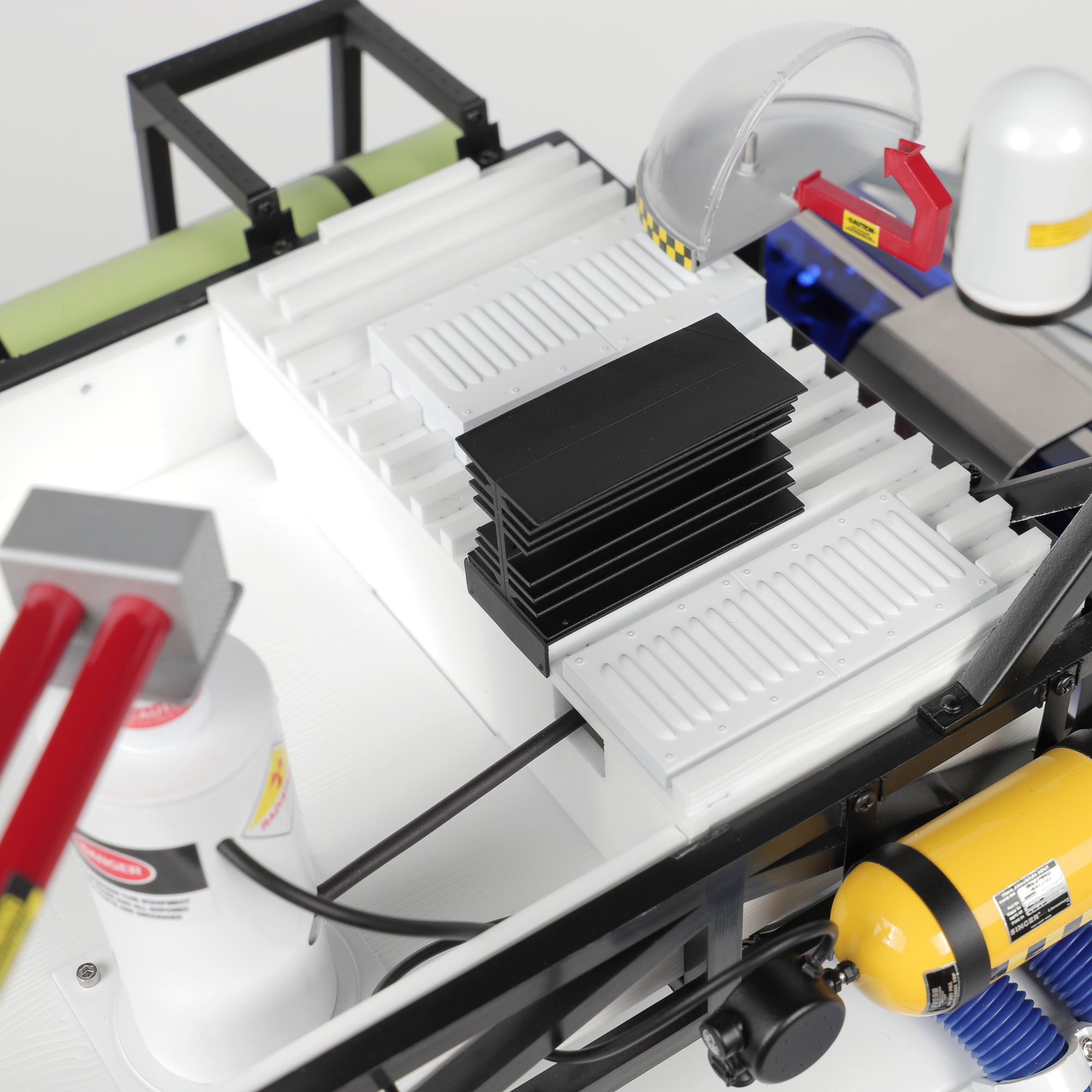
- Align the pegs on the bottom of each vent and heatsink and gently push them into position. Using a PH0 screwdriver, take 4 x ML5 screws and fit the roof vents and heatsink to the roof box lid from the underside. Be careful not to over tighten – they only need lightly tightening to hold into place!
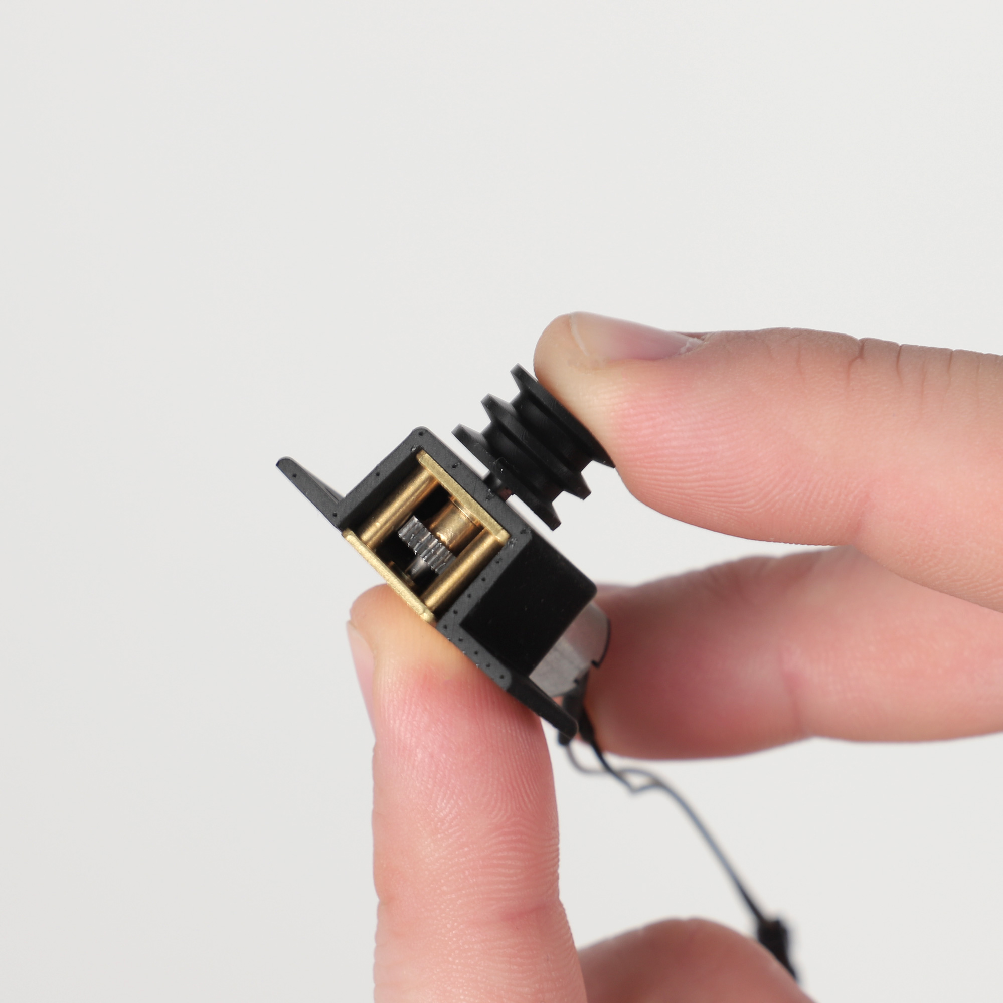
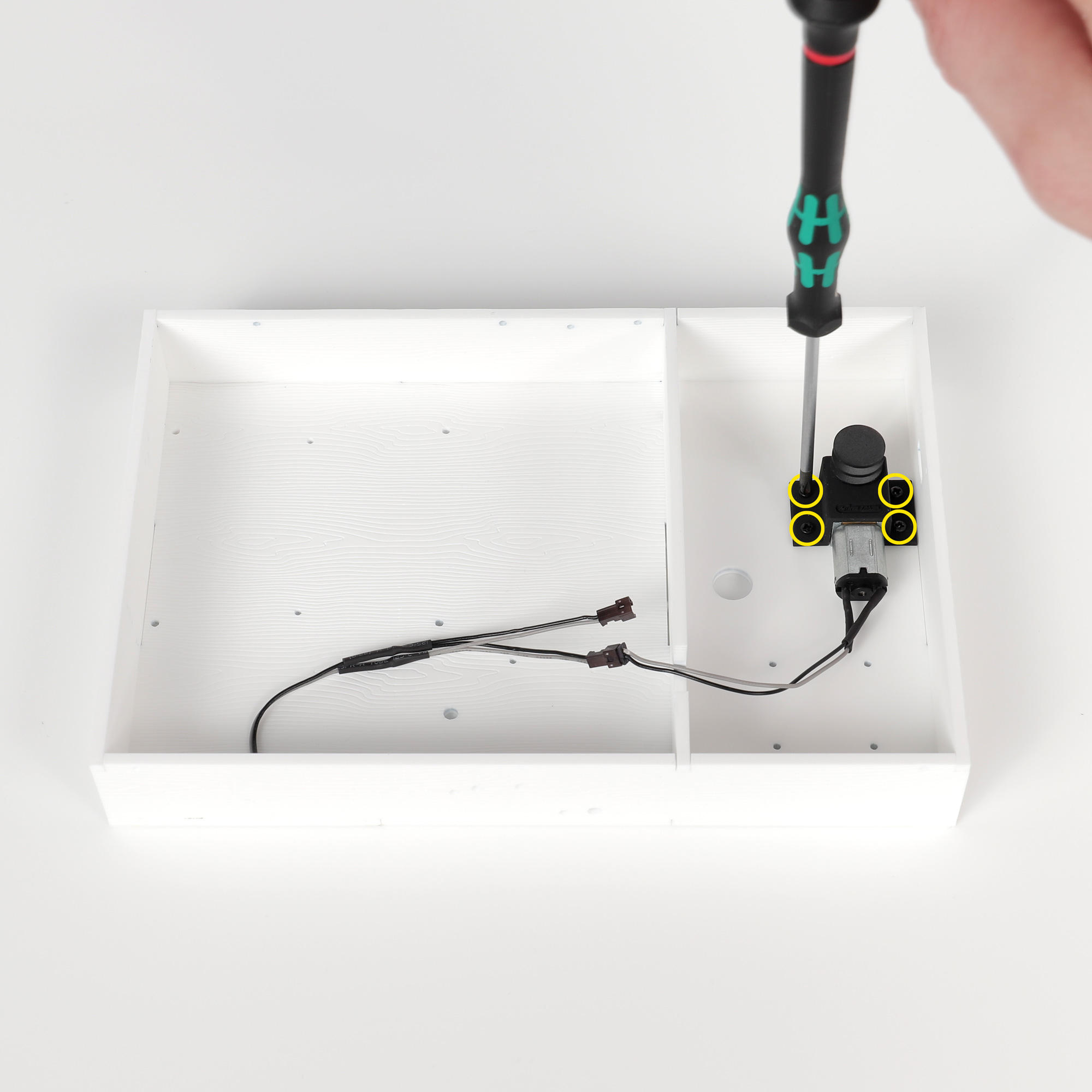
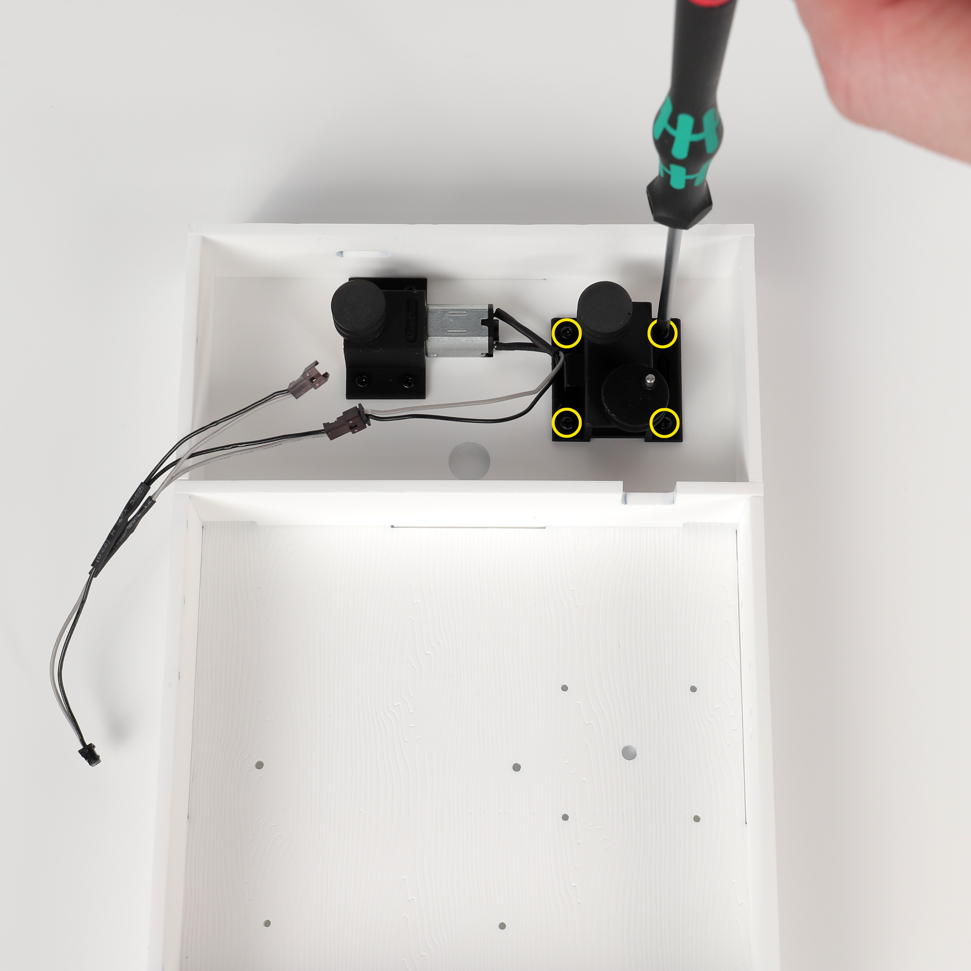
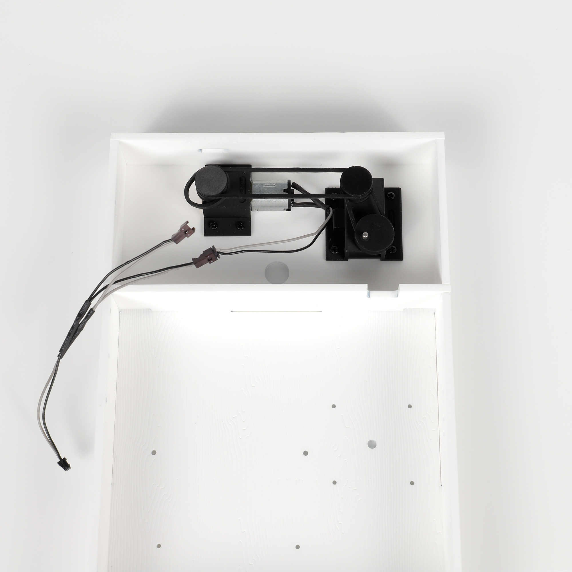
Step 3 Installing the Motor and Pulley Wheels
Step 4 Sniffer Detailing
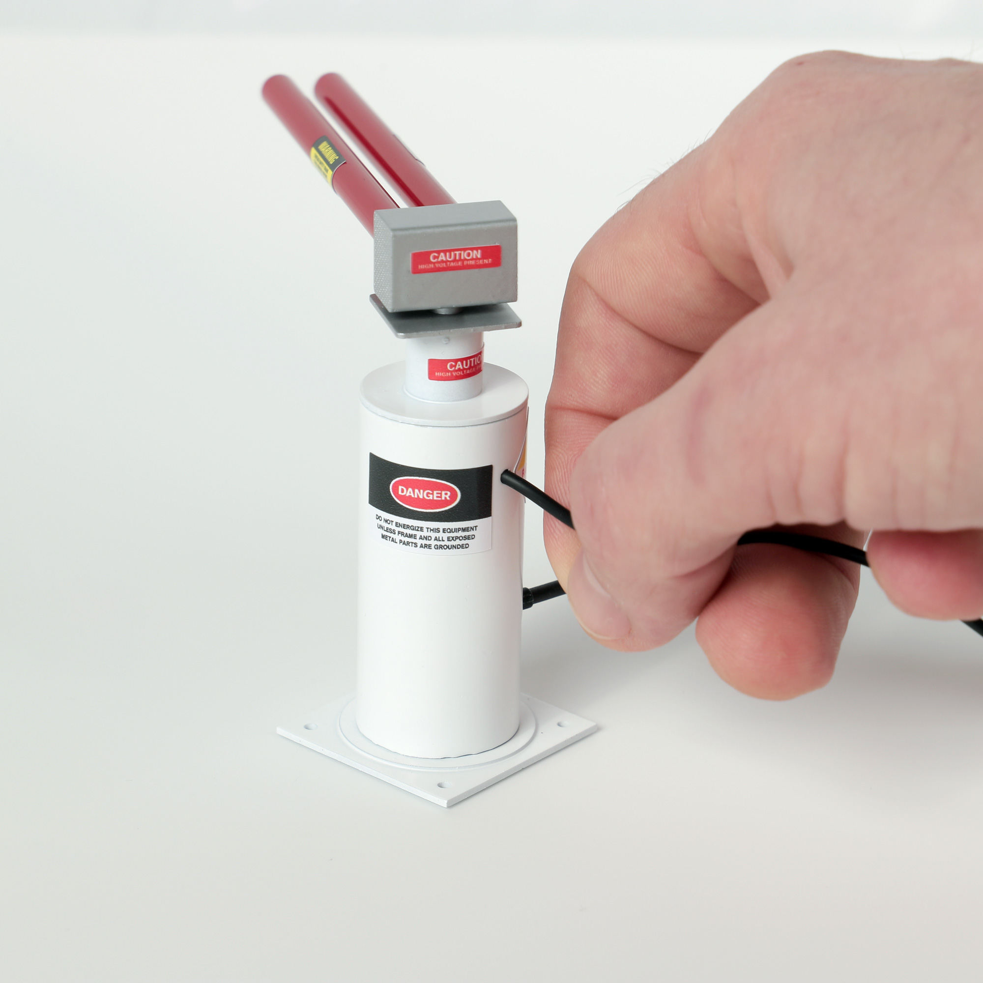
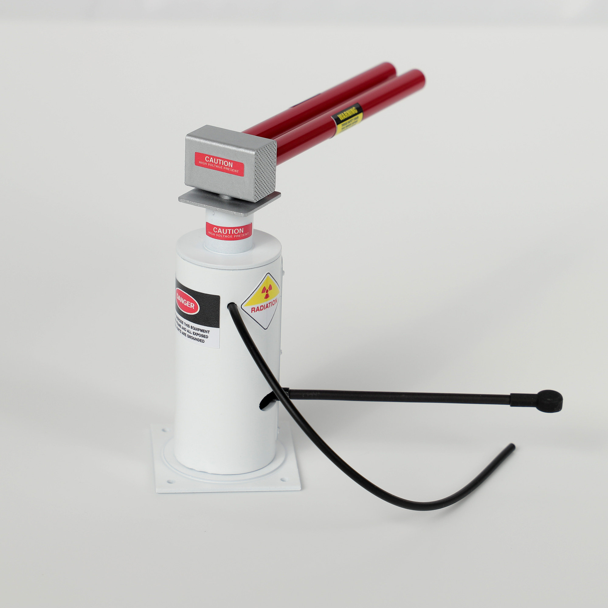
- Using a good pair of tweezers, apply sticker numbers 03, 04, 05 and 06 from the sticker sheet as per the photos. The ‘Super Boo’ and KIT-3 stickers on this sheet are just for fun, stick these where you please!
Note: DO NOT try to peel off or reposition any stickers after application – they use a permanent adhesive and may peel the paint away from the part if removed.
- Insert the sniffer side hose. There is no need to glue this part, simply insert enough so that it doesn’t fall out.
Step 5 Installing the Sniffer
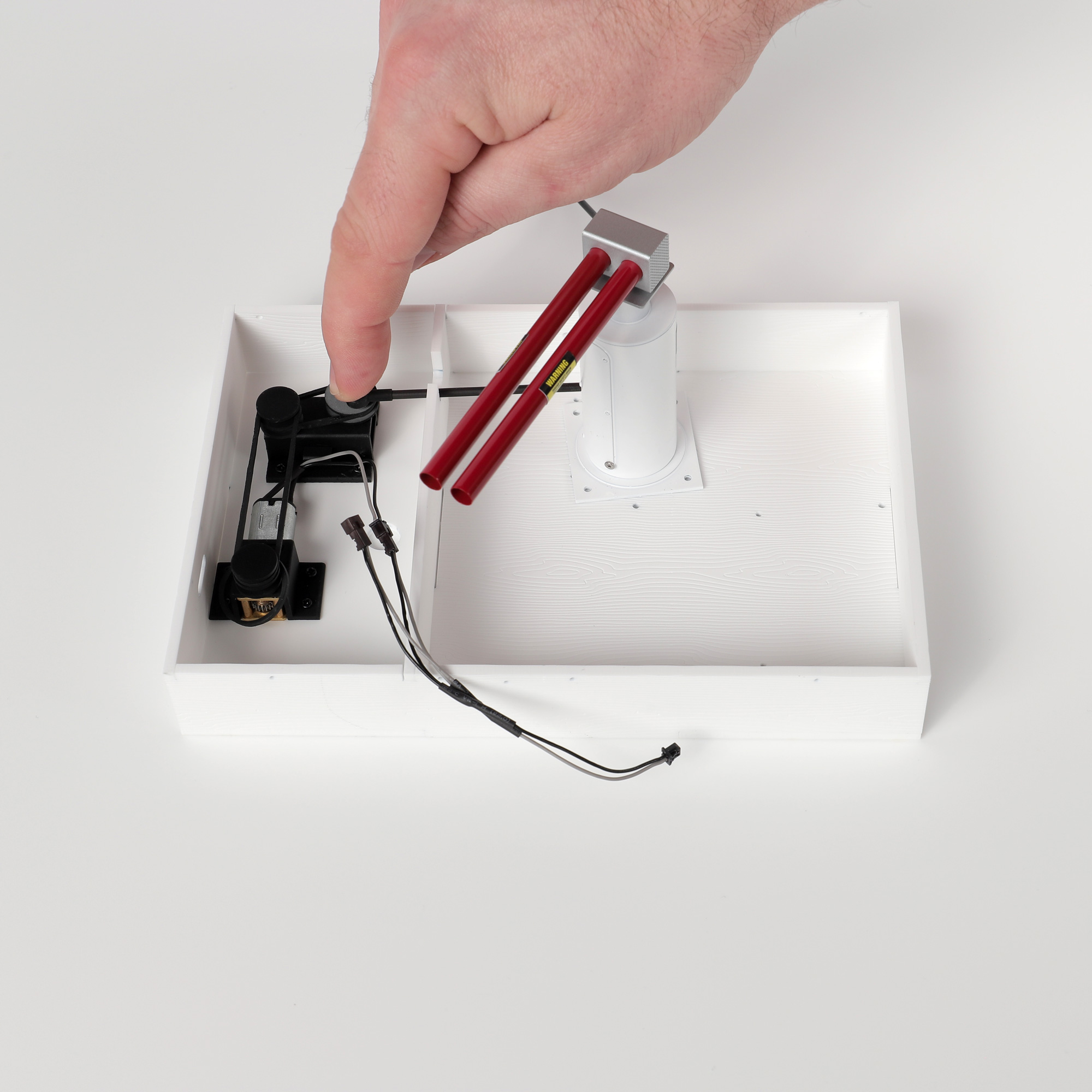
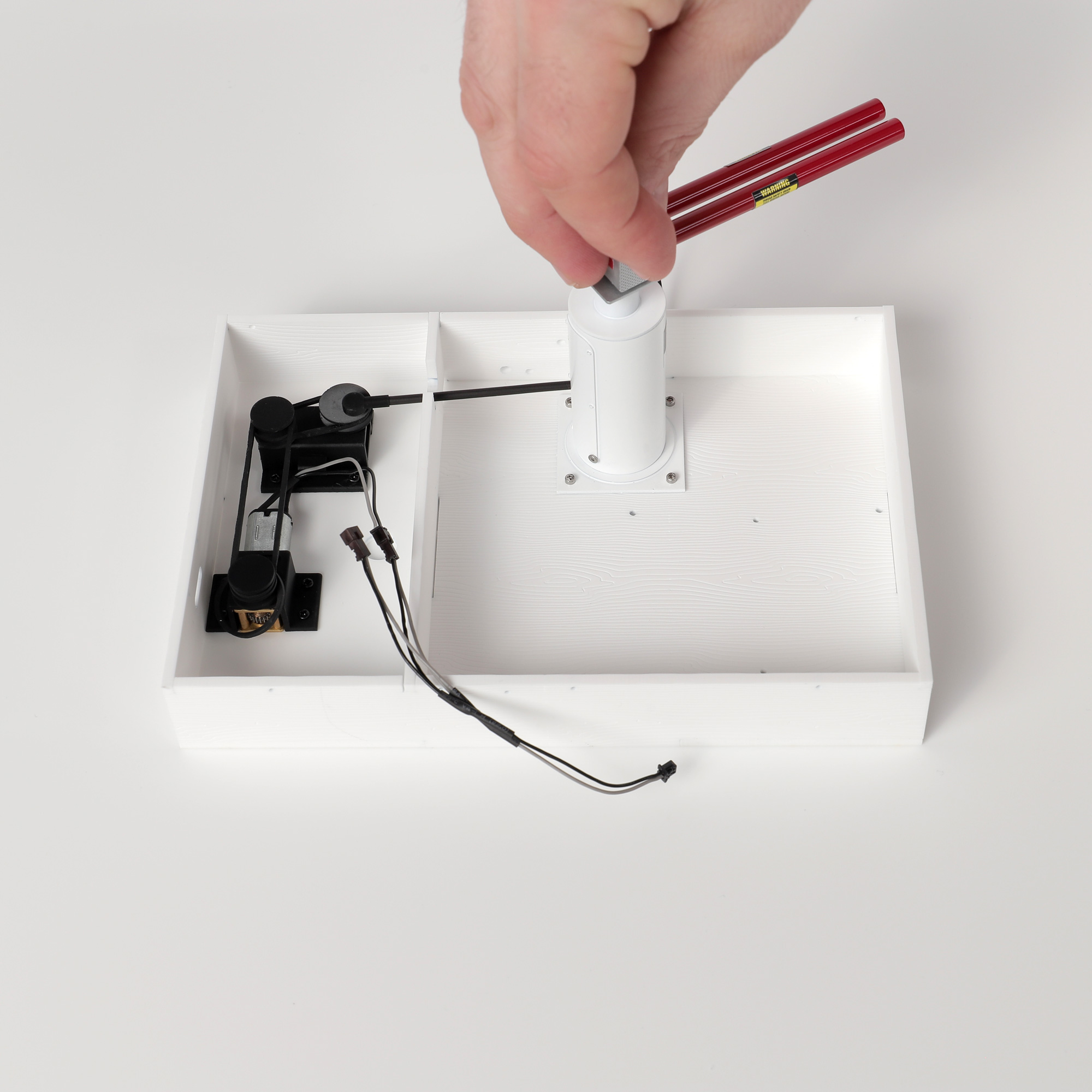
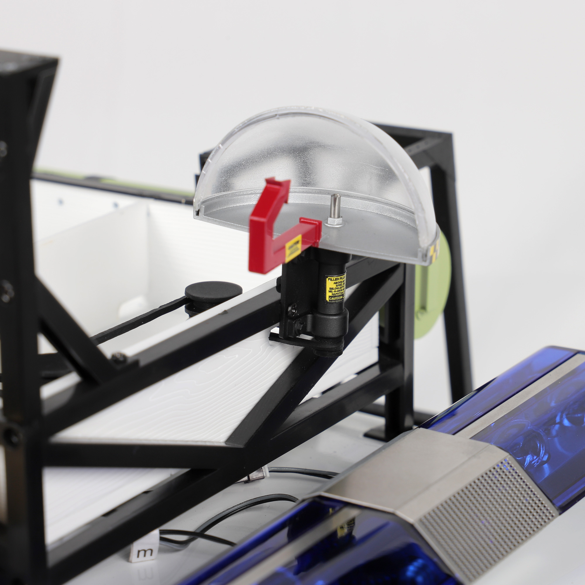
- Place the sniffer into position whilst lowering the sniffer mechanical arm onto the pulley wheel with the metal rod. The end of the mechanical arm contains a bearing and will click onto the pulley wheels rod.
Note: If the sniffers mechanical arm does become loose or fall off, you can relocate it by spinning the sniffer head and looking for the small metal rod inside the sniffer body. Then, simply place it over the metal rod to relocate.
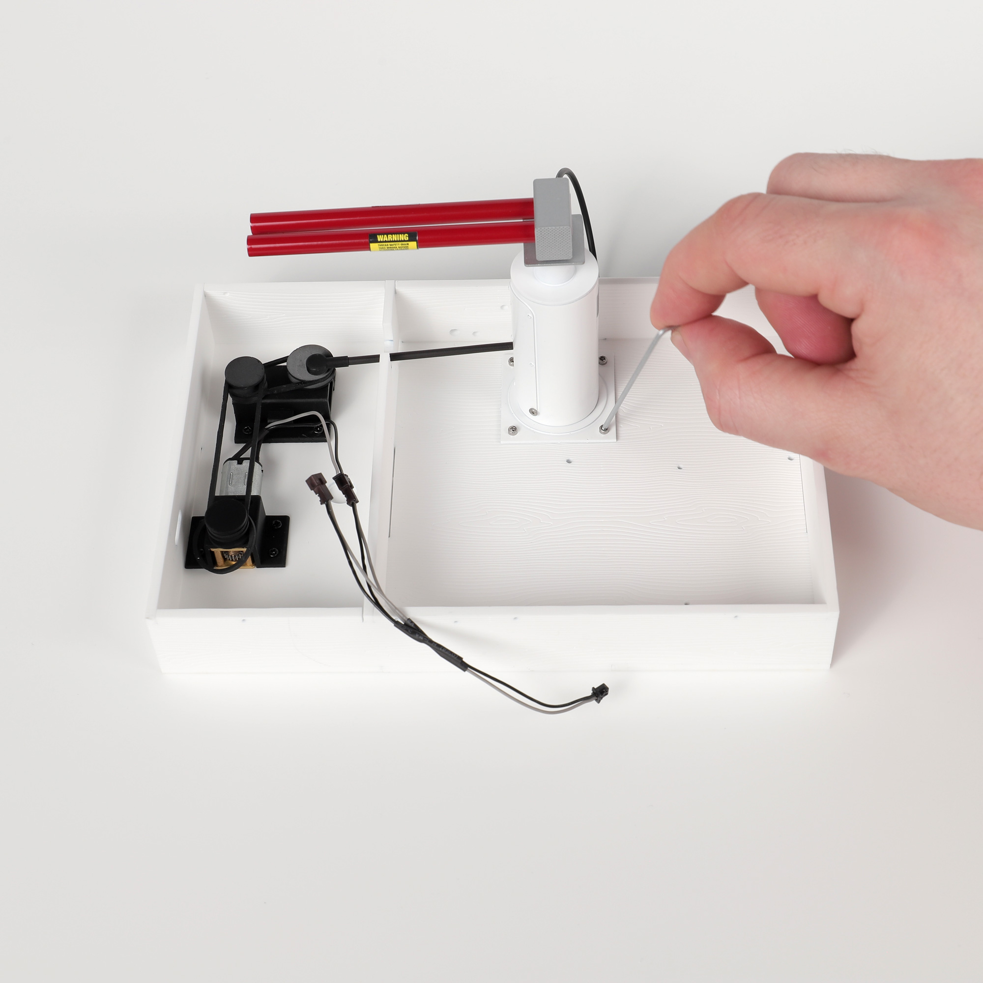
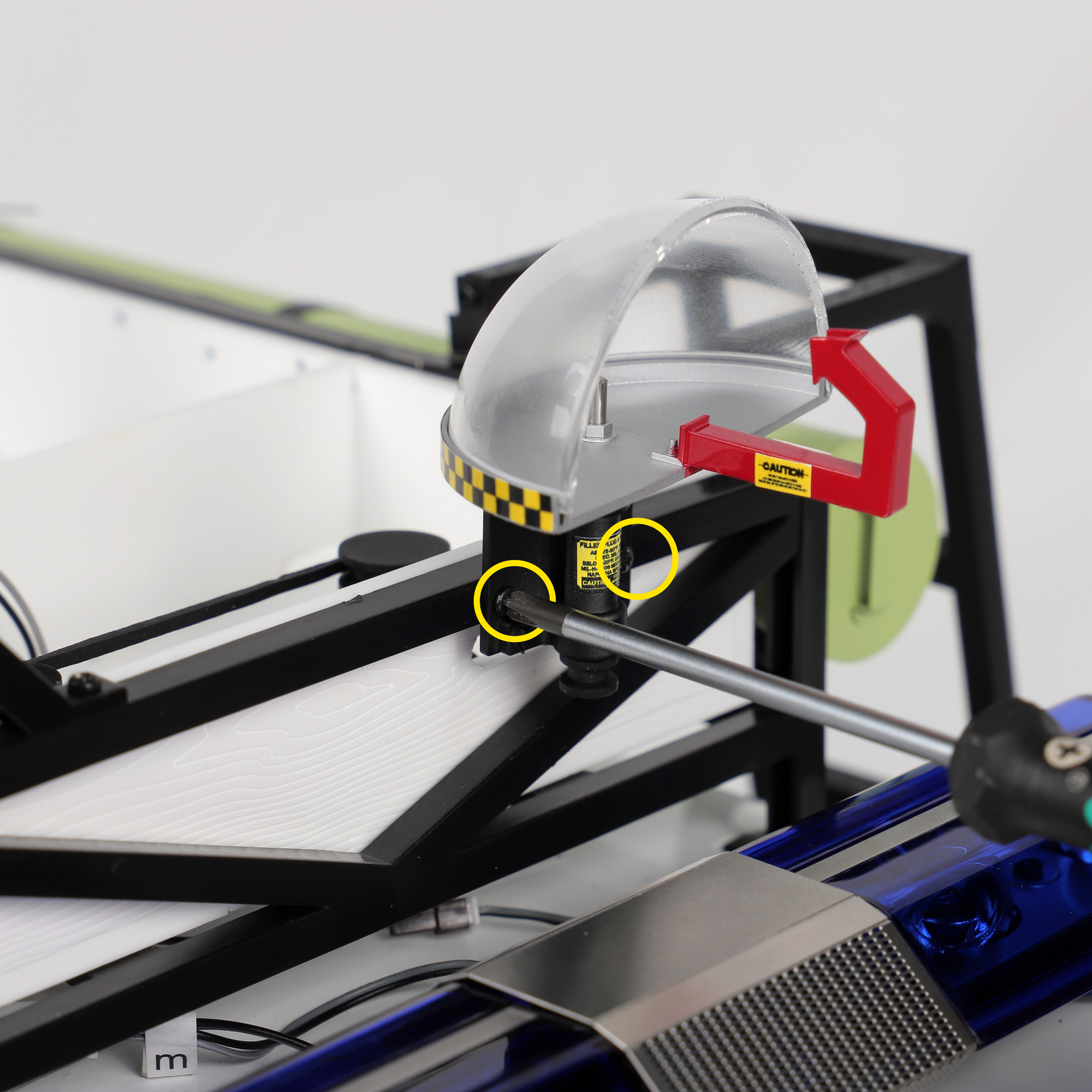
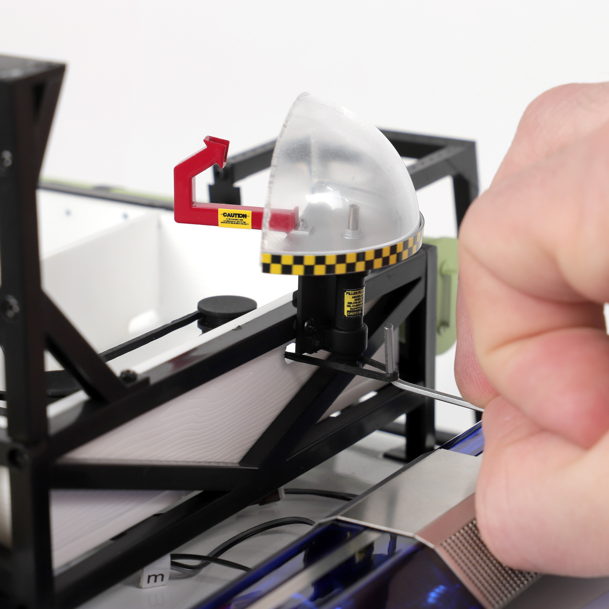
- Using the 1.5mm Wera hex key provided, take 4 x ML6 Hex bolts and fix the sniffer base to the roof box. Hold the base steady as you fix and be careful not to scratch the sniffer base with the key key. The Wera tool will work at an angle in difficult to reach areas as well as upright. Be careful not to over tighten.
- Once the sniffer is mounted to the roof box, and the mechanical arm is secured on both ends, you can gently spin the sniffer head and tubes to point forwards. The sniffer head can be moved again later on to fine tune it’s motion. Ensure that you turn the model off and stop the motion between adjustments.
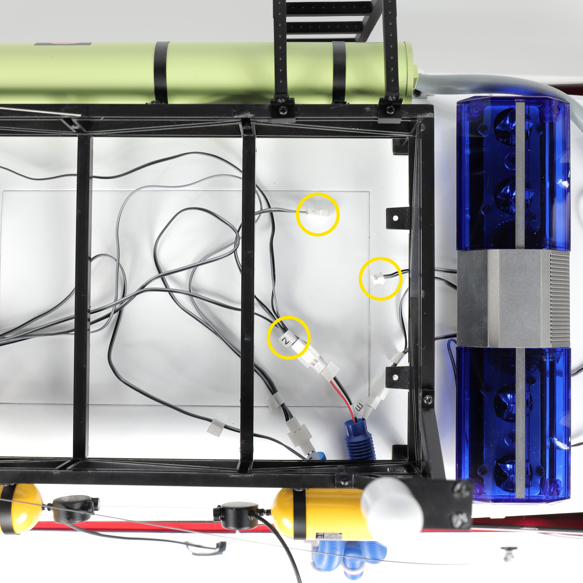
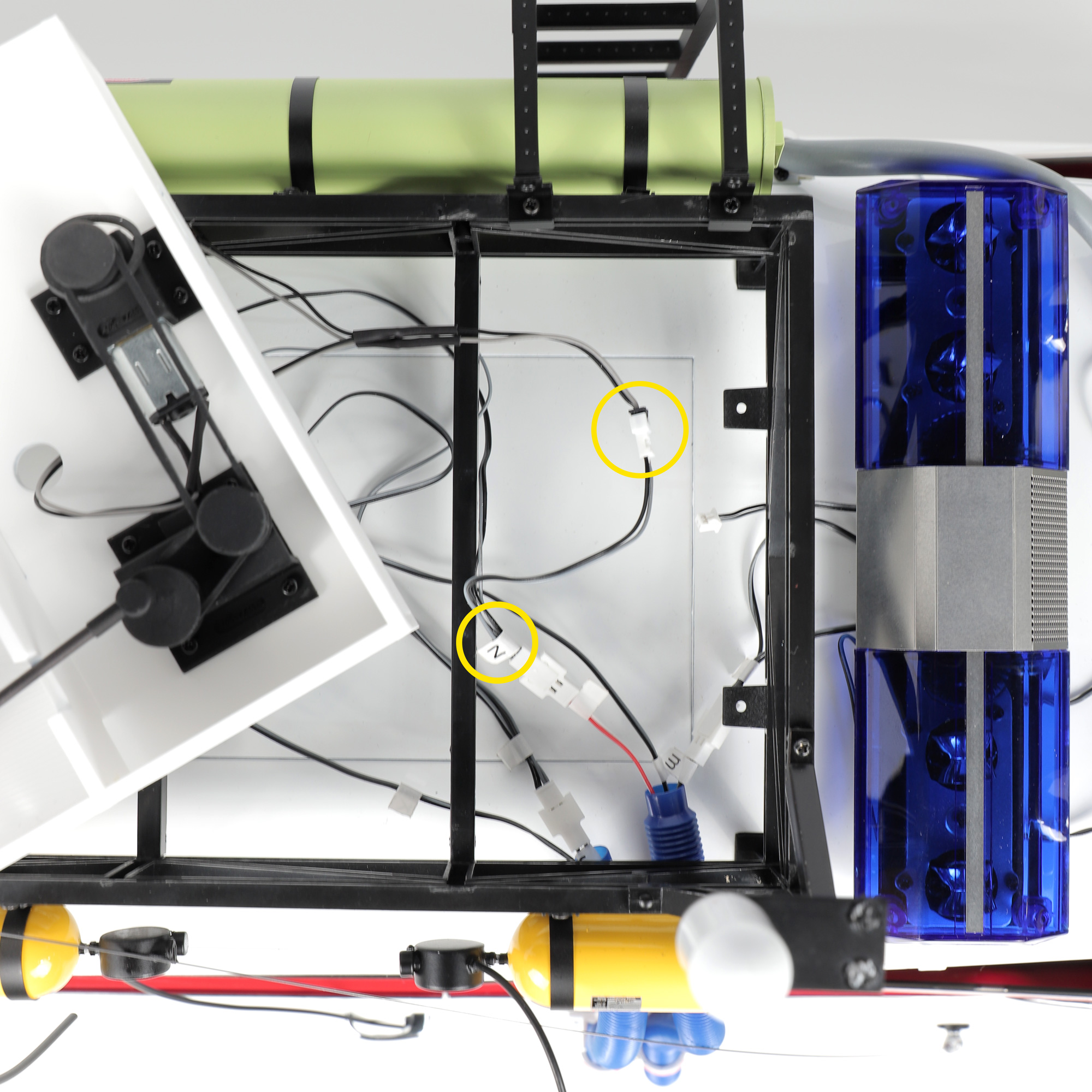
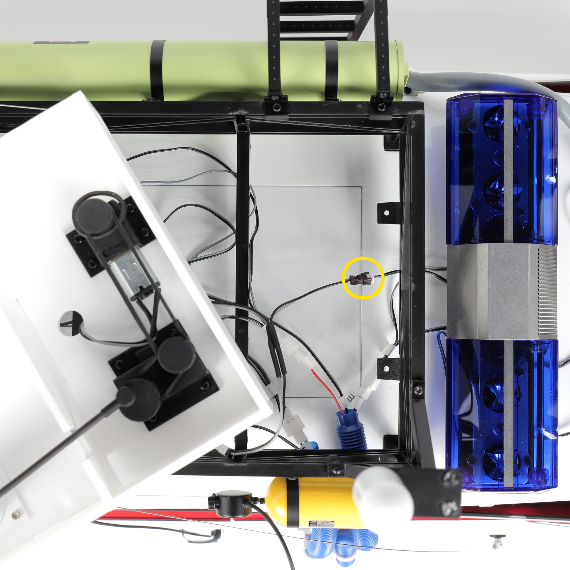
Step 6 Connecting Power
Step 7 Fitting the Roof Box inside the Roof Rack
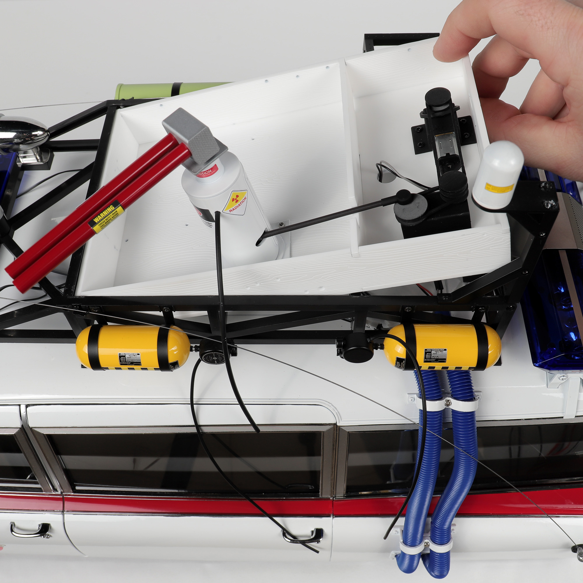
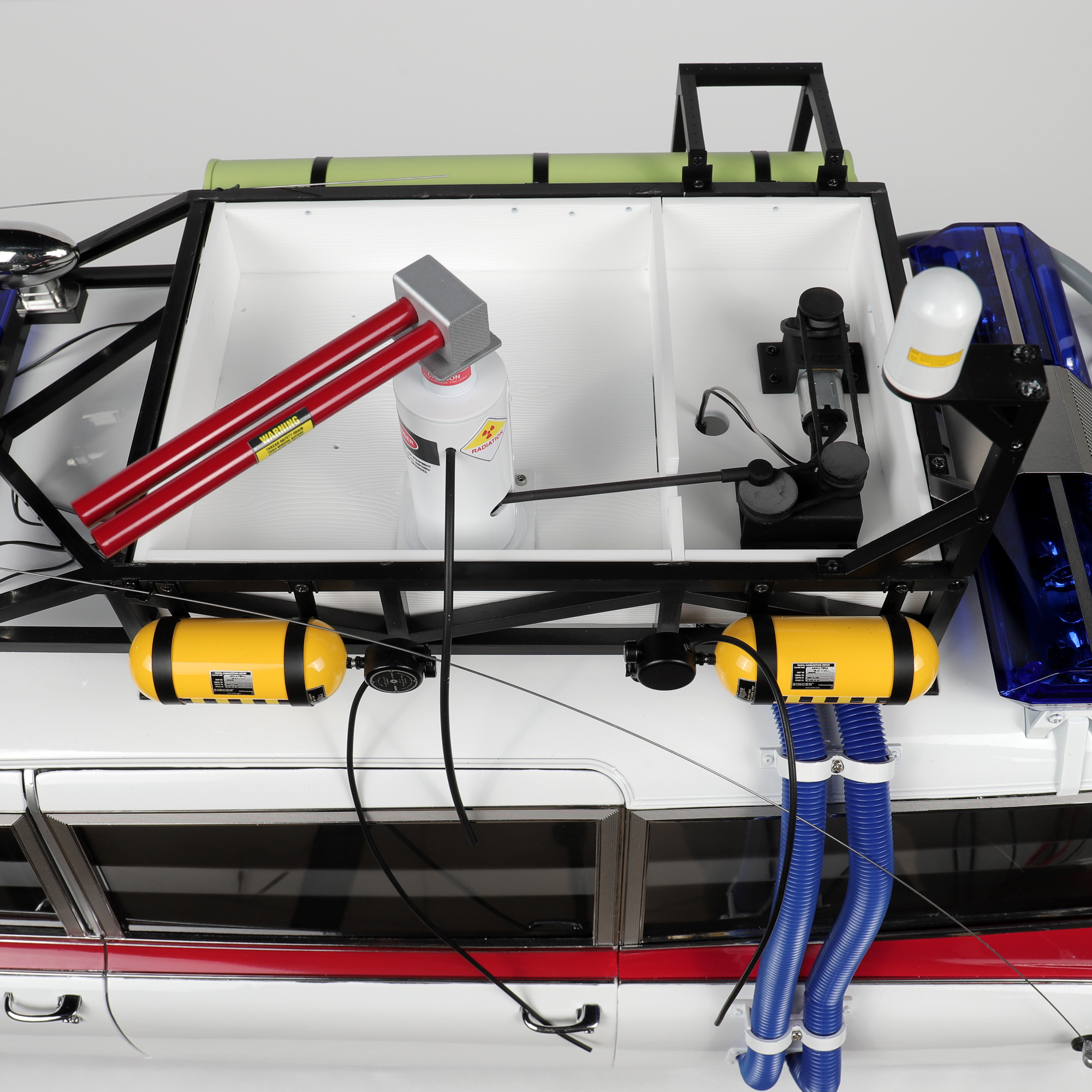
- Place the roof box inside the roof rack, with the motor and pulleys towards the back of the Ecto-1. Check that the box isn’t laying on any trapped cables.
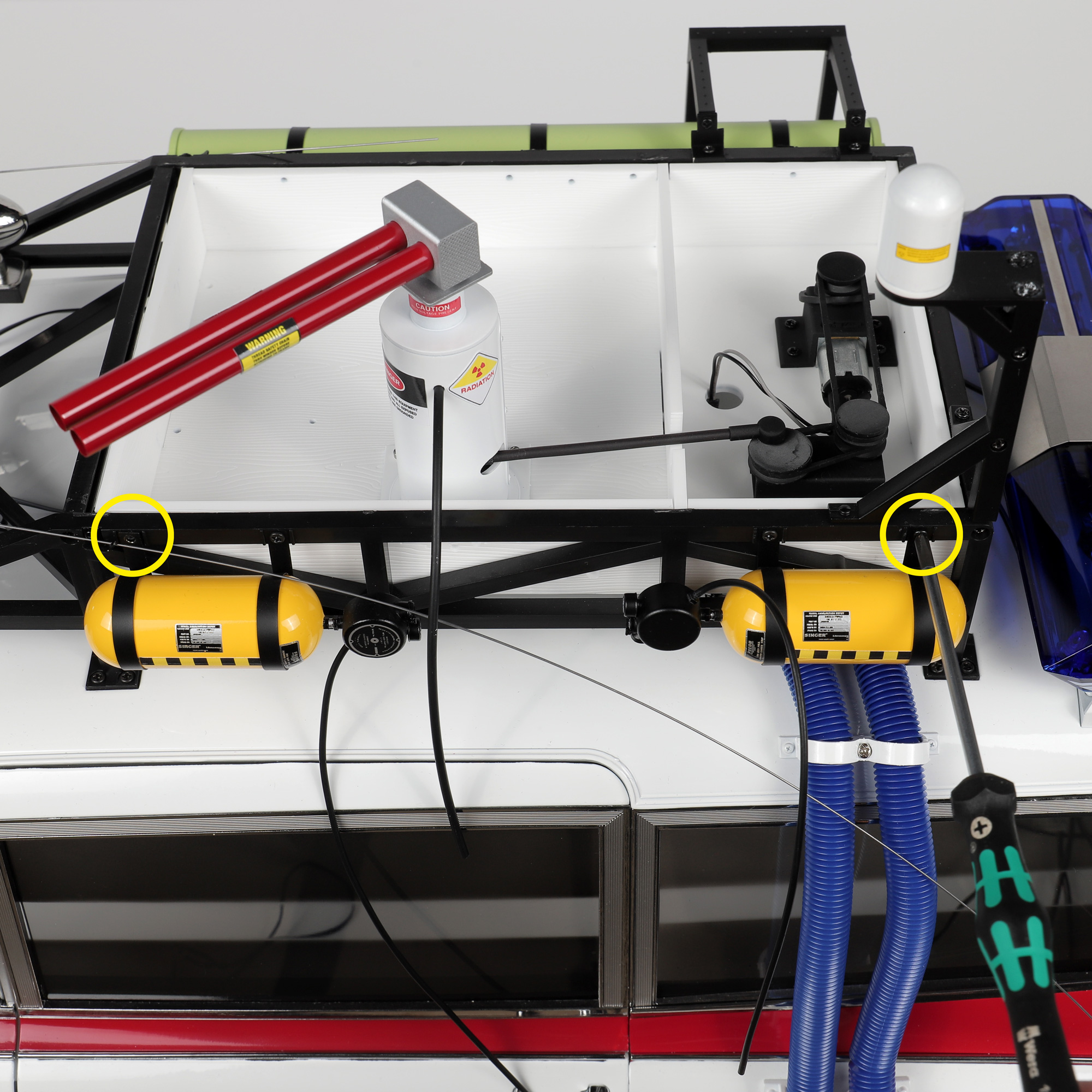
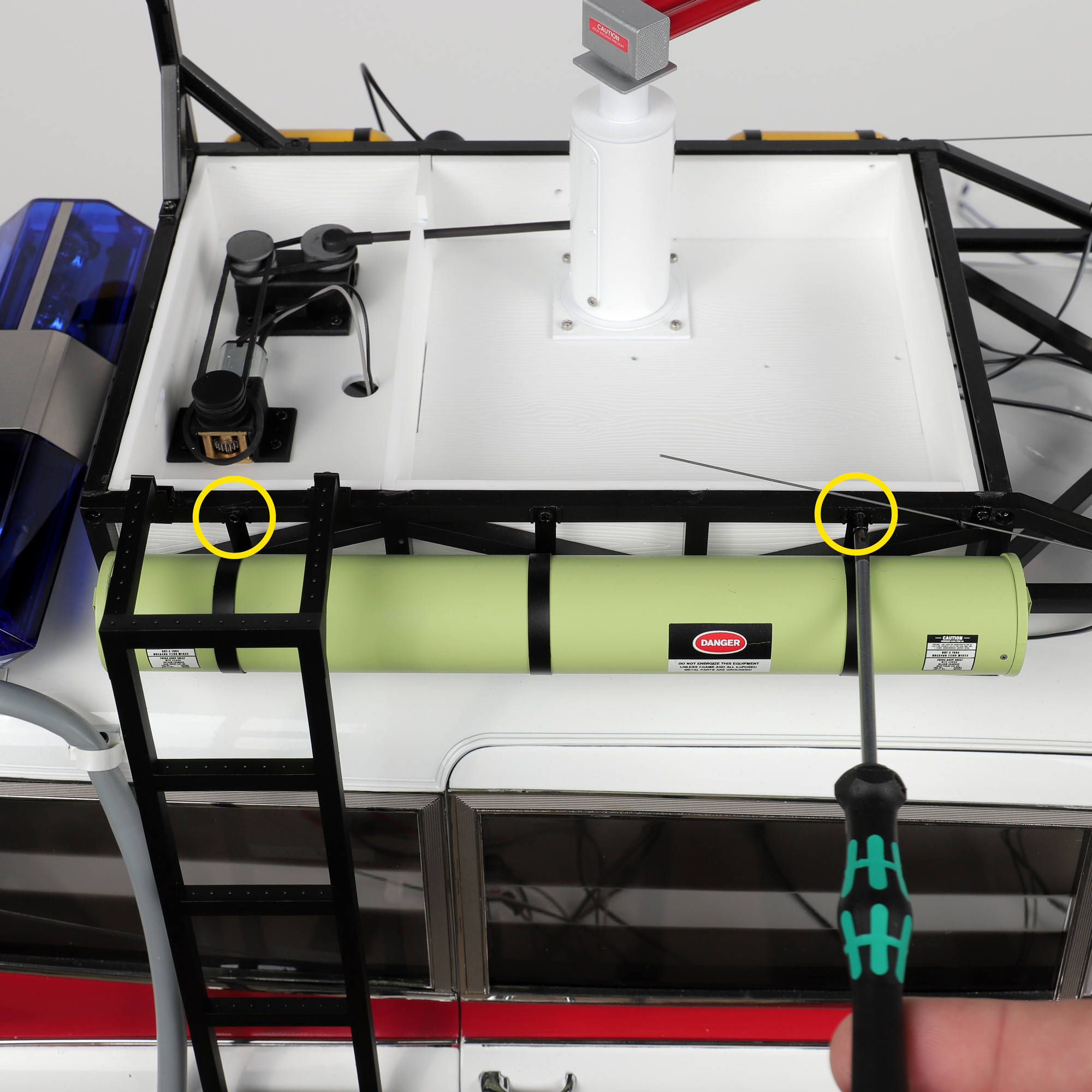
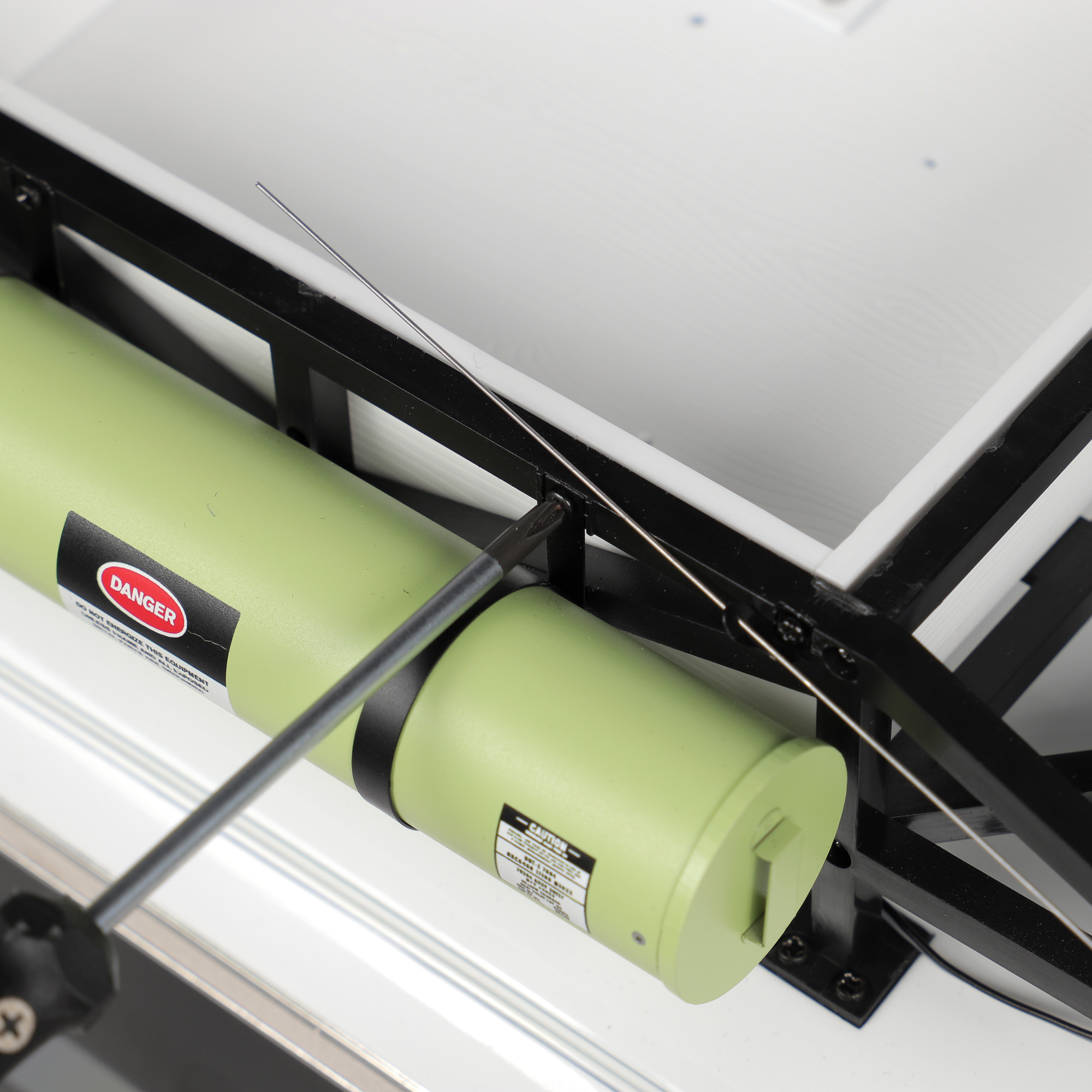
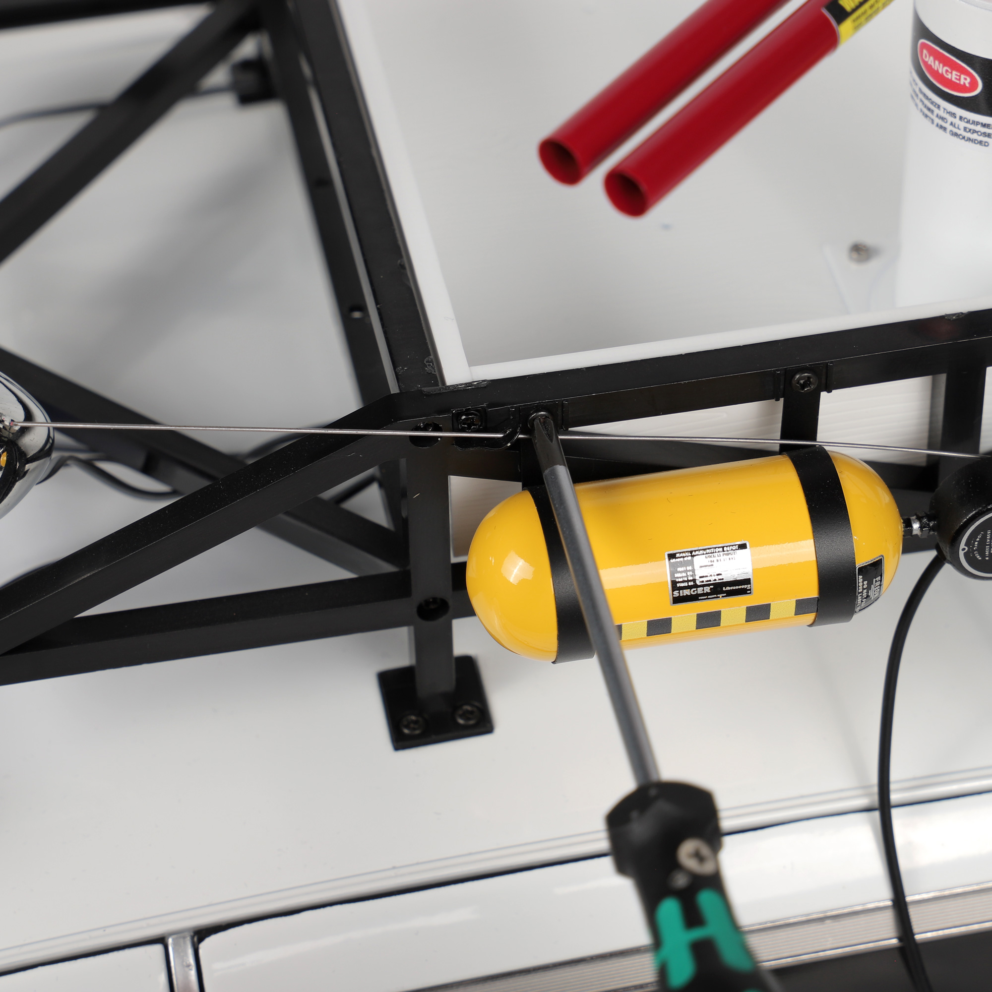
- Remove the 4 x ML1 screws from the outer brackets holding the Green Tube and Freon Tubes in place. We will utilise these holes to fix the roof box into place. You can keep these screws as spares for future projects.
- Using a PH0 screwdriver, take 4 x ML8 screws and fix through the same Green Tube and Freon Tube brackets and holes. With these longer screws we will screw through and into the roof box. Check alignment with the hole in the roof box whilst tightening each. Screw with equal pressure and amount around the box to avoid the box being pulled more against one side. Be careful not to over tighten.
Step 8 Applying the Radar Dish Stickers
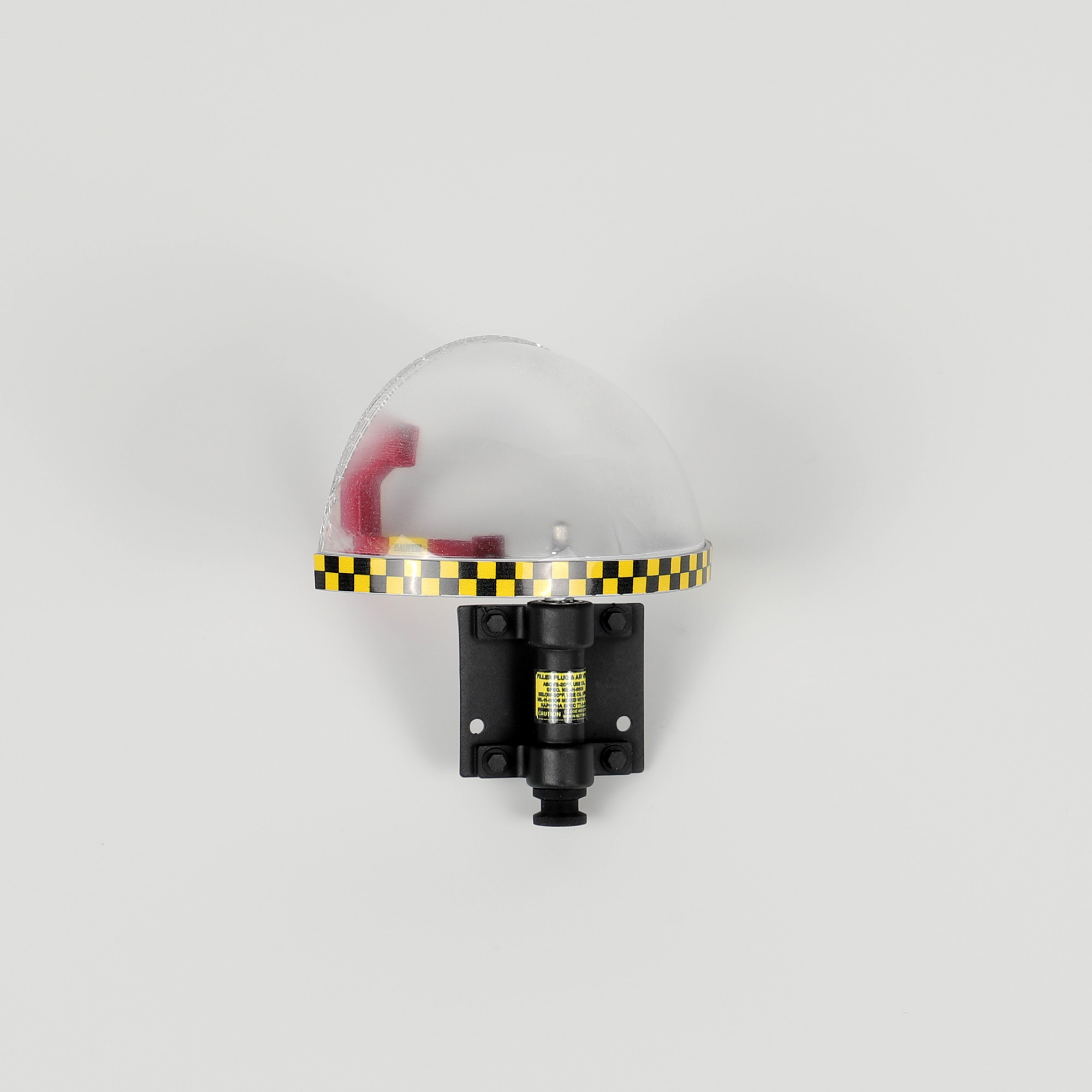
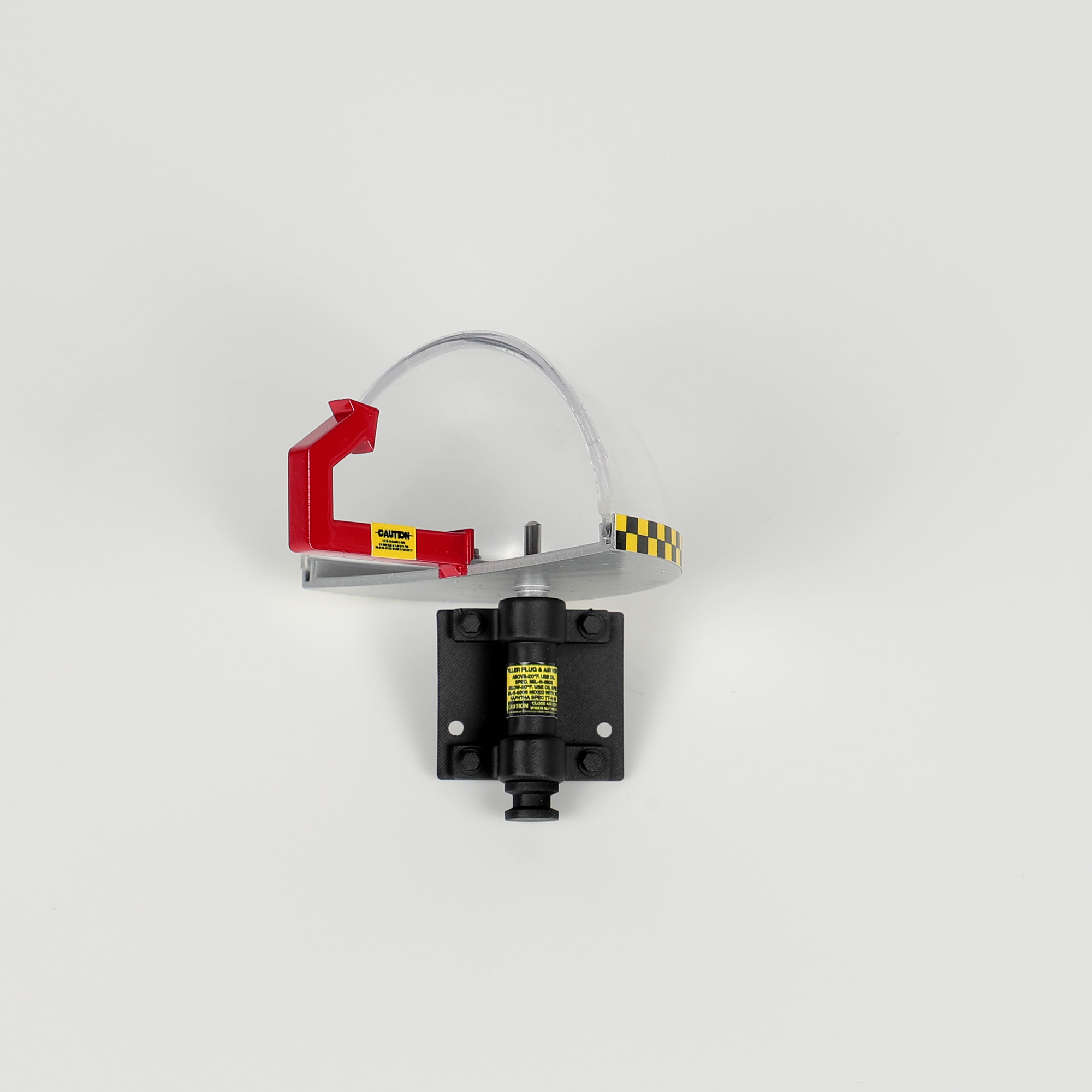
- Using a good pair of tweezers, apply sticker numbers 01, 02 and 08 from the sticker sheet as per the photos. Try not to stretch the chequered vinyl sticker as you wrap around the base of the Radar Dish.
Note: DO NOT try to peel off or reposition any stickers after application – they use a permanent adhesive and may peel the paint away from the part if removed.
Step 9 Fitting the Radar Dish
- Hook the radar dish mount over the roof rack frame. Then, using a PH0 screwdriver, take 2 x ML8 screws and fix the radar dish mount to the side of the roof rack using the existing holes. With these long screws, we will again screw through the mount and roof rack, and into the roof box. If the holes don’t seem to line up with your Radar mount, it is because you’ve tightened the roof box too much to one side of the roof rack. Loosen off and adjust until the holes for the Radar Mount line up.
- Using the short end of the Wera Hex Key tool, hook the Radar Dish pulley belt through the hole and position onto the Radar Dish pulley wheel.
Step 10 Hose and Cable Management
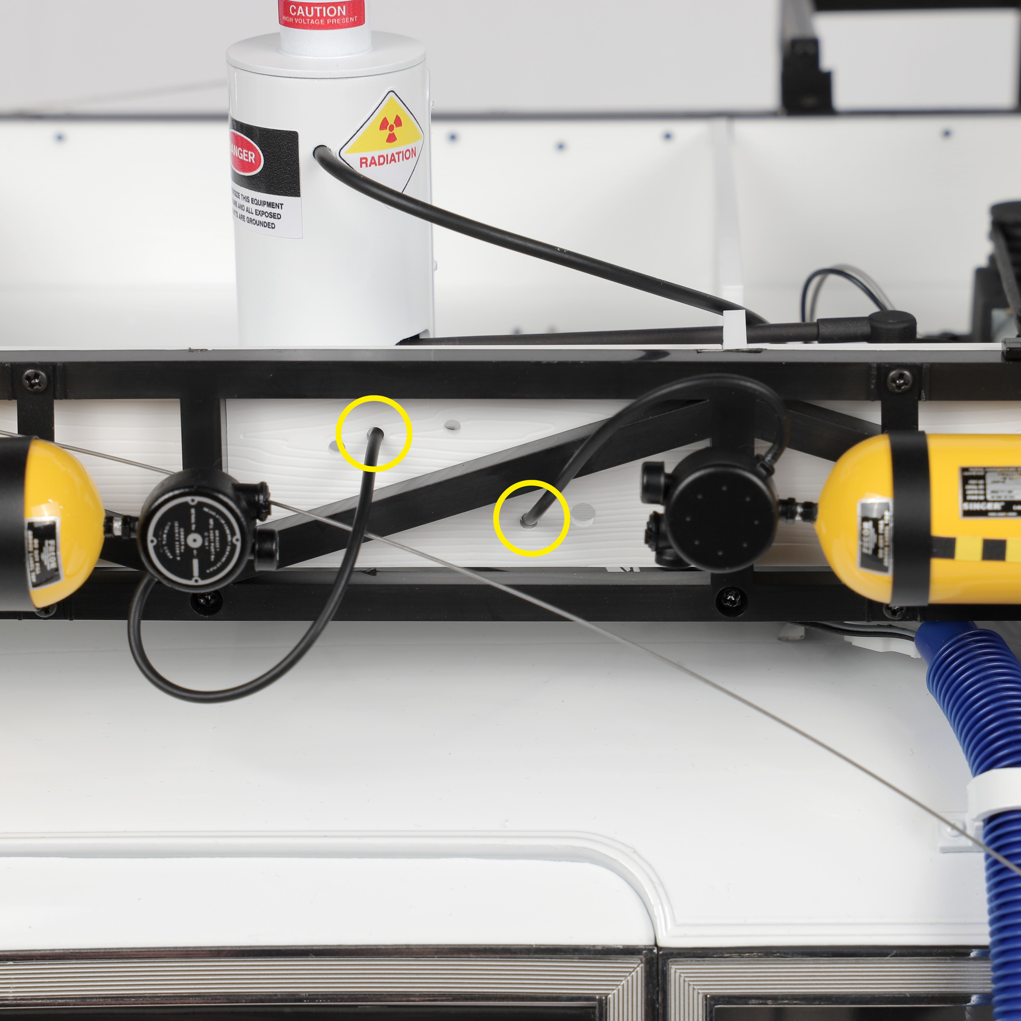
- Feed the hoses from the Oxygen Tanks through the holes in the side of roof box as demonstrated. Now feed the hoses from the Sniffer and Oxygen Tanks through the hole leading into the motor compartment. You will also notice a small hook on the side of the Sniffer pulley wheel mount, this is to secure the power cable from the motor. Hook the motor cable under this hook.
Step 11 Fitting the Roof Box Lid
- Insert the roof box lid in and under the Radar Dish, then lower into position. This lid has been designed to be removable to give easy access to the motor and pulley mechanisms.
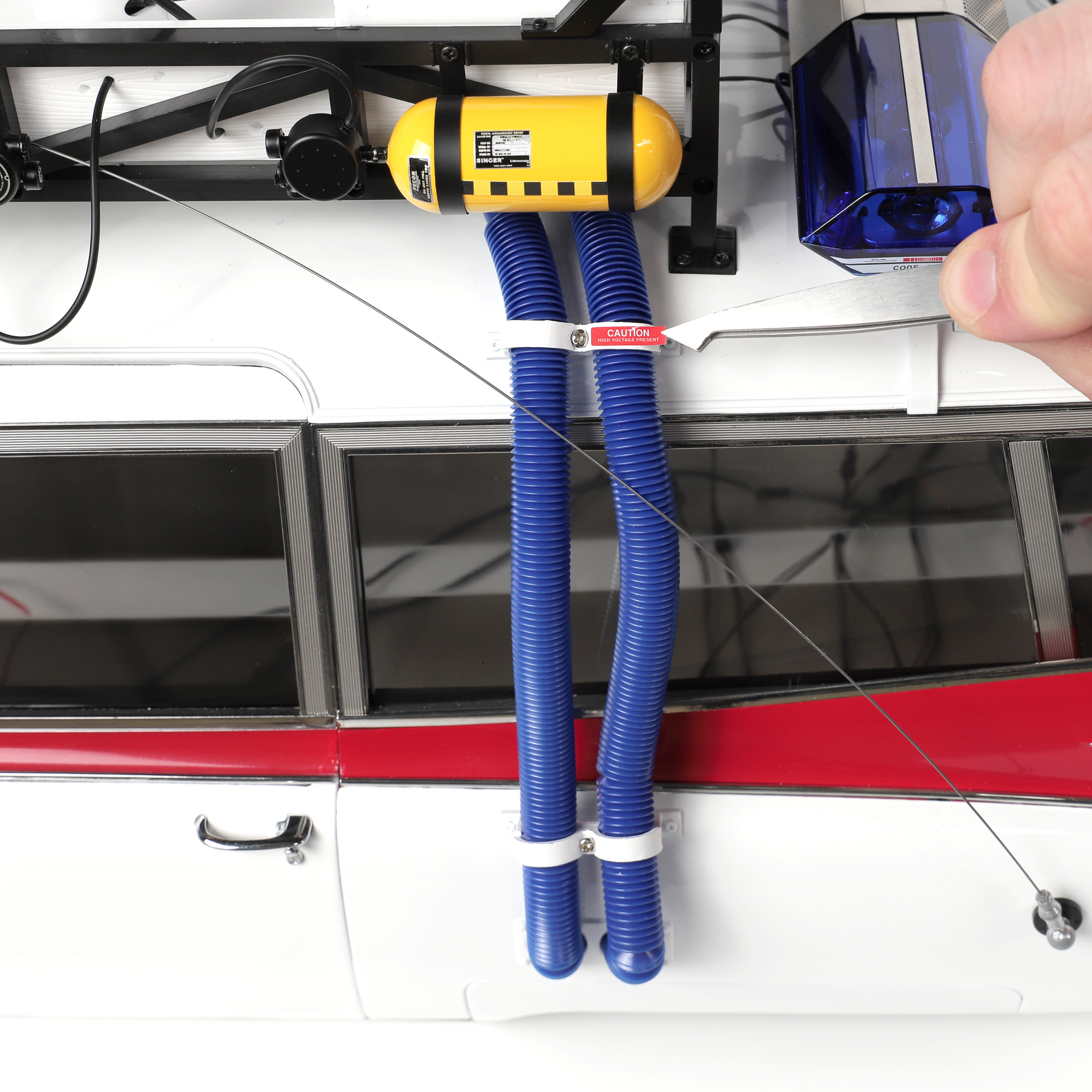
Final Step Blue Hose Detailing
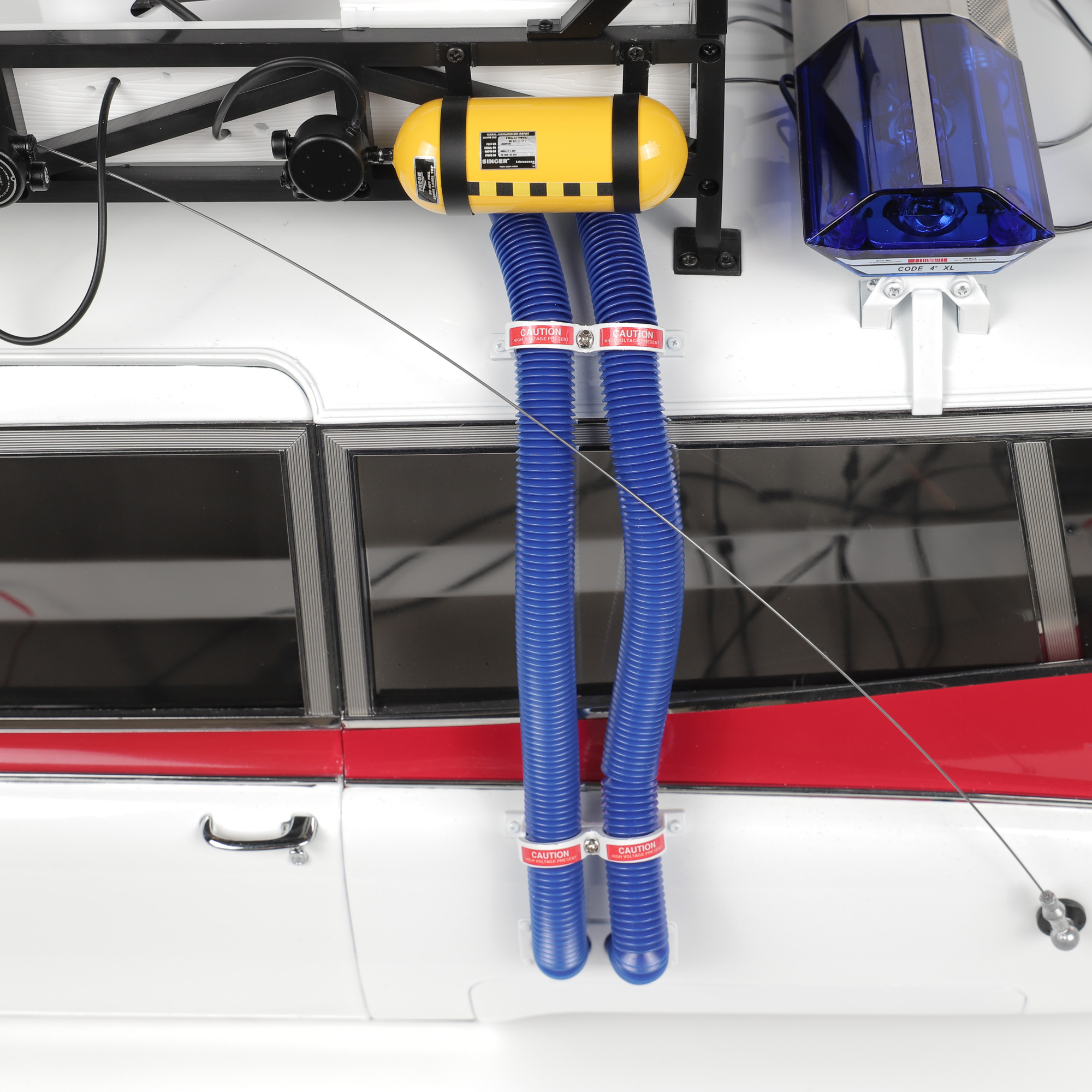
- Included within this kit are the missing CAUTION stickers for the blue hose brackets. Using a good pair of tweezers, apply four sticker numbers 04 from the sticker sheet as per the photos.


