Installing the Resurrect the Ecto-1 Kit 4

Installing the Resurrect the Ecto-1 Kit 4

Resurrect the Ecto-1 Kit 4 contents list

Step 1 Detailing the HVAC Unit

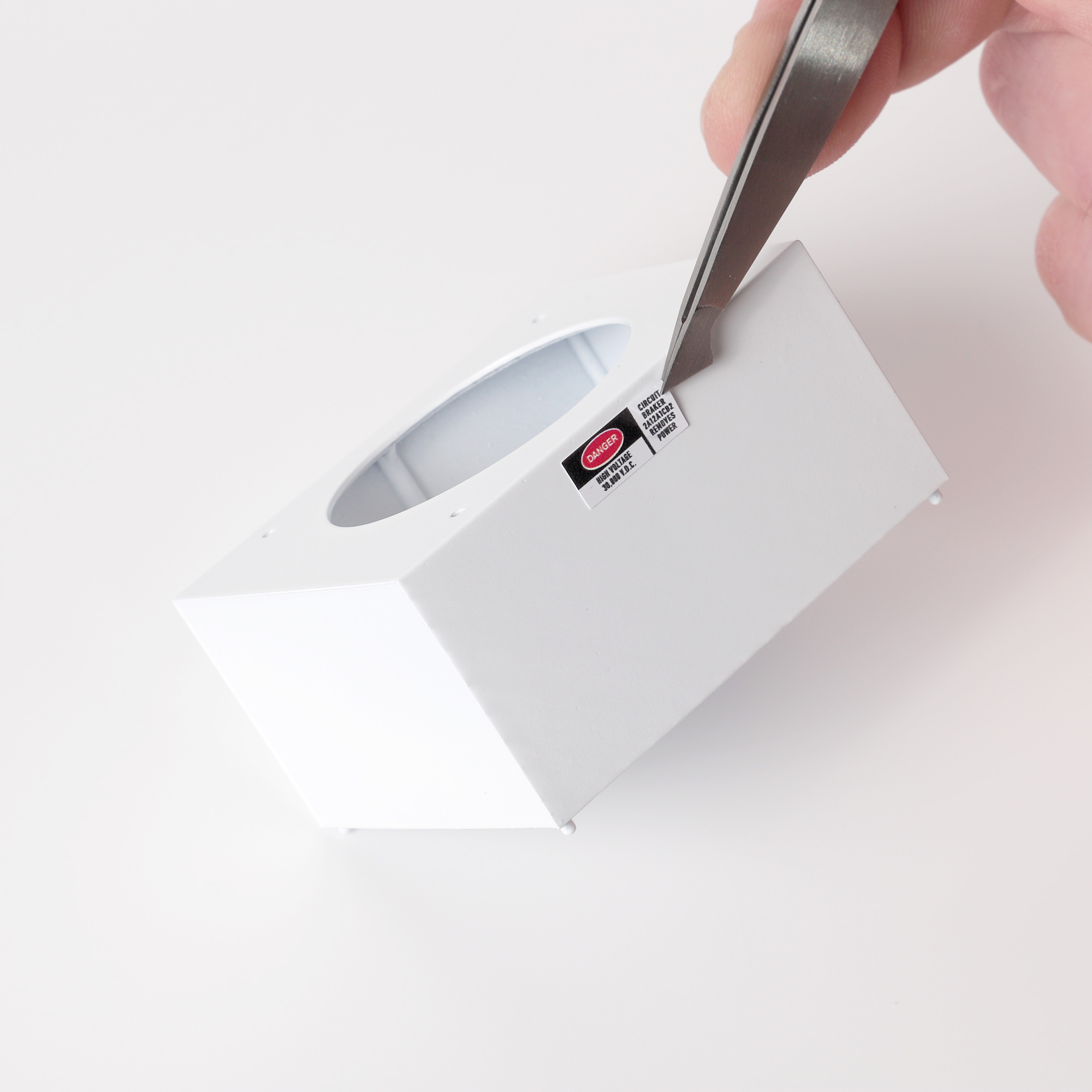
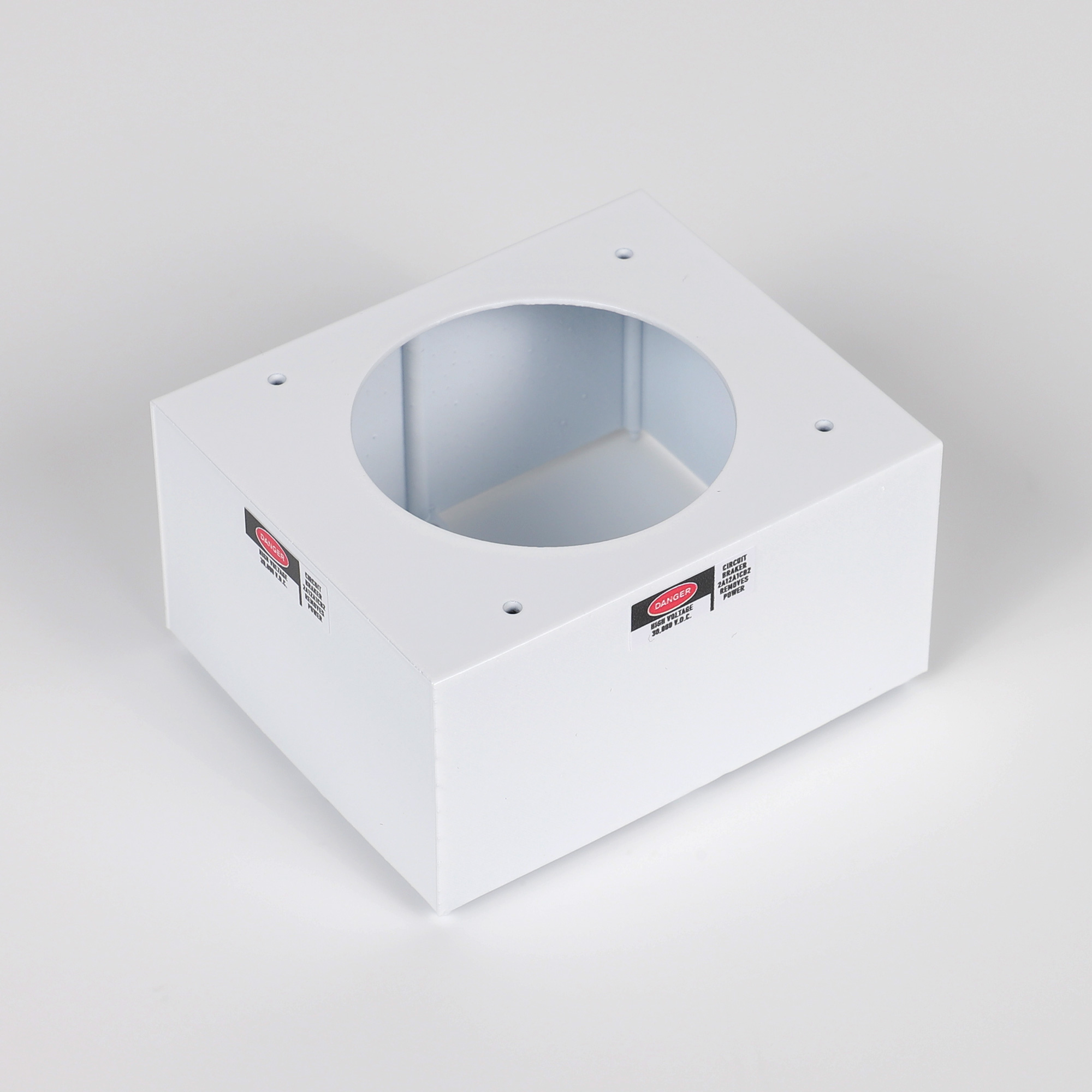
  1. Optional ‘DANGER’ stickers are provided for the HVAC unit. They appear on later/restored Ecto-1’s but not on the original. For the purposes of this guide I will install them to show you where they need to be positioned. Using a good pair of tweezers, apply 2 x ‘DANGER’ stickers to the HVAC box – one on the plain side with no vents and the other on the front side with no vents.

Note: DO NOT try to peel off or reposition any stickers after application – they use a permanent adhesive and may peel the paint away from the part if removed.

Applying DANGER stickers to HVAC unit with tweezers
HVAC unit with DANGER stickers applied to sides

Step 2 Installing the HVAC Unit

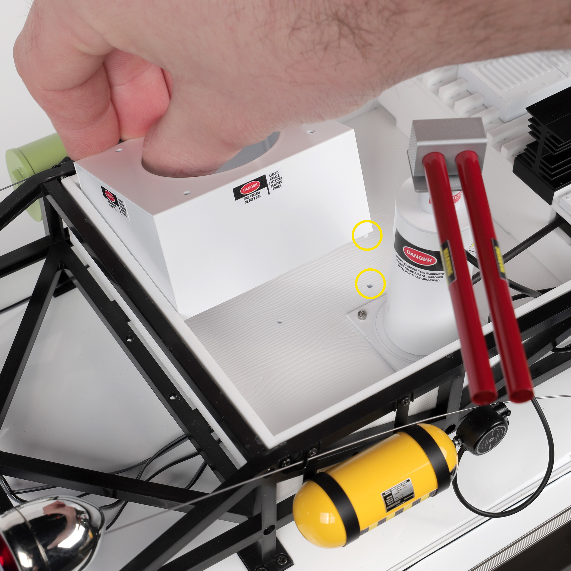
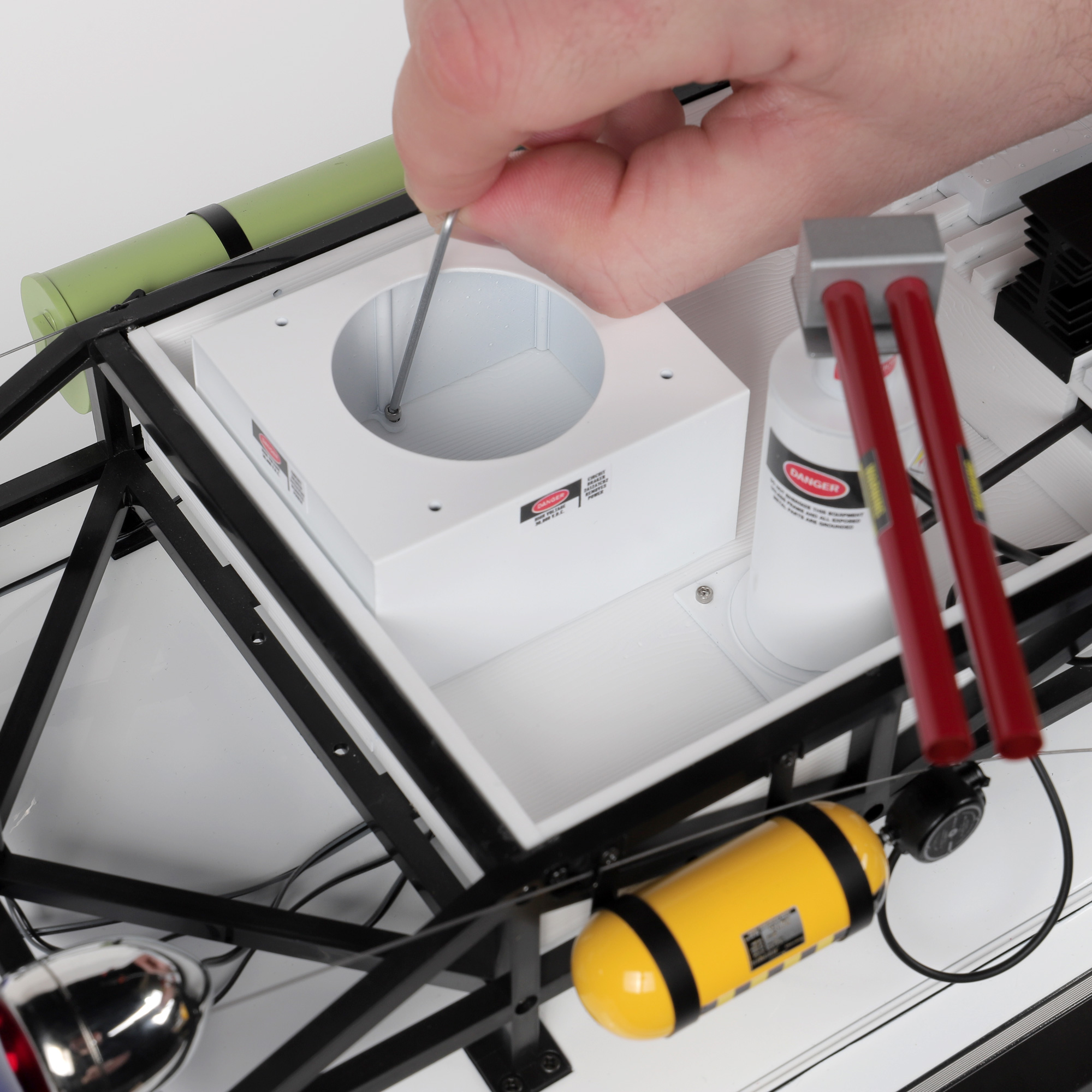
  1. Locate and lower the pins on the bottom of the HVAC box into their correct positions in the roof box. Push securely into place. Then, using a good set of tweezers, insert 2 x ML6 Hex bolts into position inside the HVAC box. Using the 1.5mm Wera hex key provided, fix the HVAC box to the roof box. The Wera tool will work at an angle in difficult to reach areas as well as upright.  Be careful not to over tighten.
Locating pins on the bottom of HVAC box
Securing HVAC box in roof box
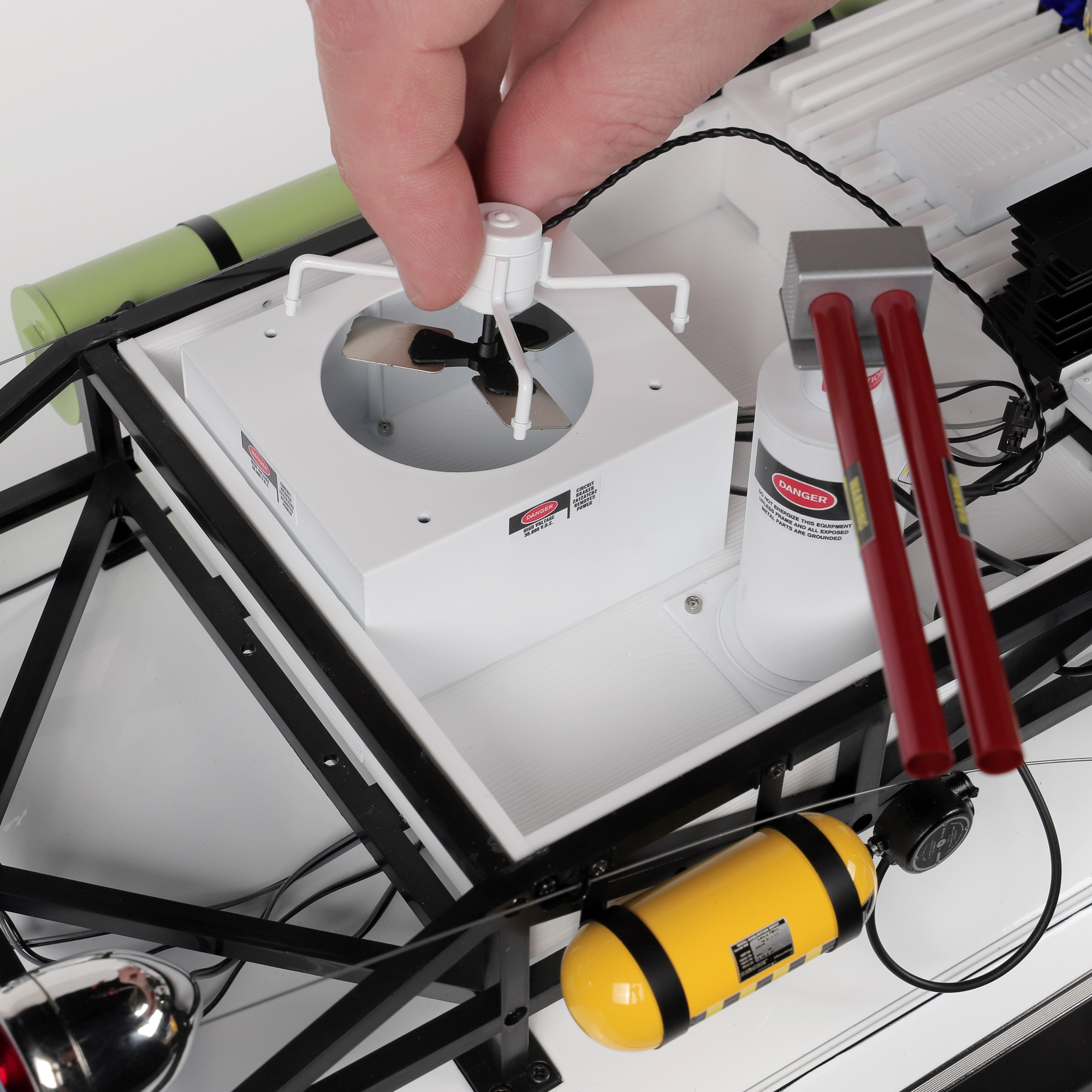
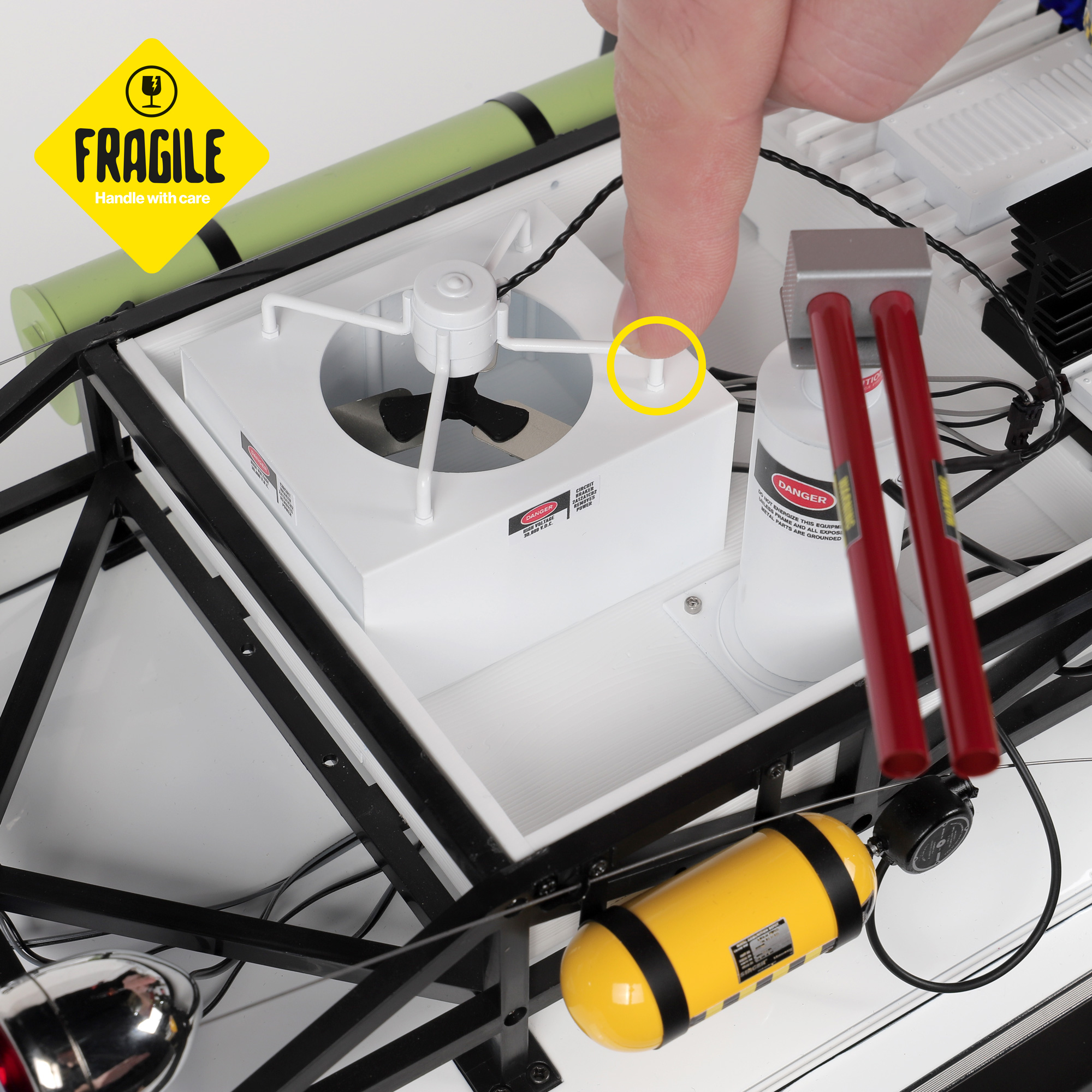
  1. FRAGILE PART – HANDLE WITH CARE! The legs on this part are very fragile, be careful not to make the legs flex in any way or they may break! You will notice that the holes towards the rear of the HVAC are closer together than the holes at the front. This matches the original Ecto-1. Ensure the fan assembly is oriented correctly to match these holes. Insert the fan blades slightly sideways into the hole in the top of HVAC box and then position the legs of the fan assembly over the correct holes. Take the fan assembly and carefully insert the pins from each leg, only pushing into place directly over the pin and hole. No glue is required for this stage.
Orienting HVAC fan assembly correctly
Inserting HVAC fan assembly pins

Step 3 Connecting Power to the HVAC Unit

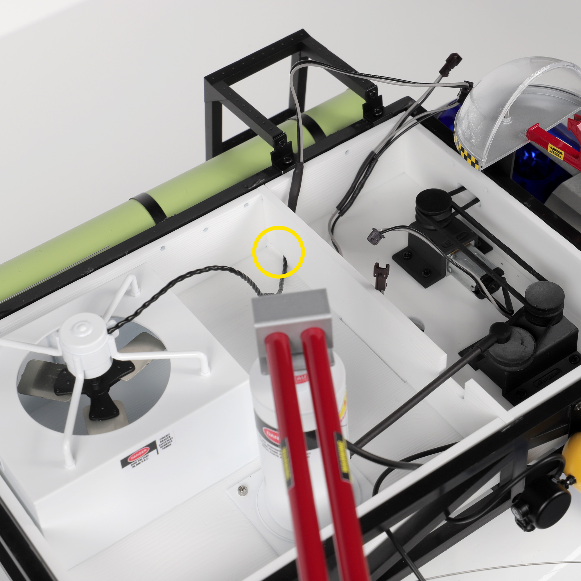
Running cables from HVAC fan under into hole in motor compartment
  1. Remove the lid from the roof box and place to one side in a safe place. Run the cables from the HVAC fan under and through the allocated hole in the motor compartment.
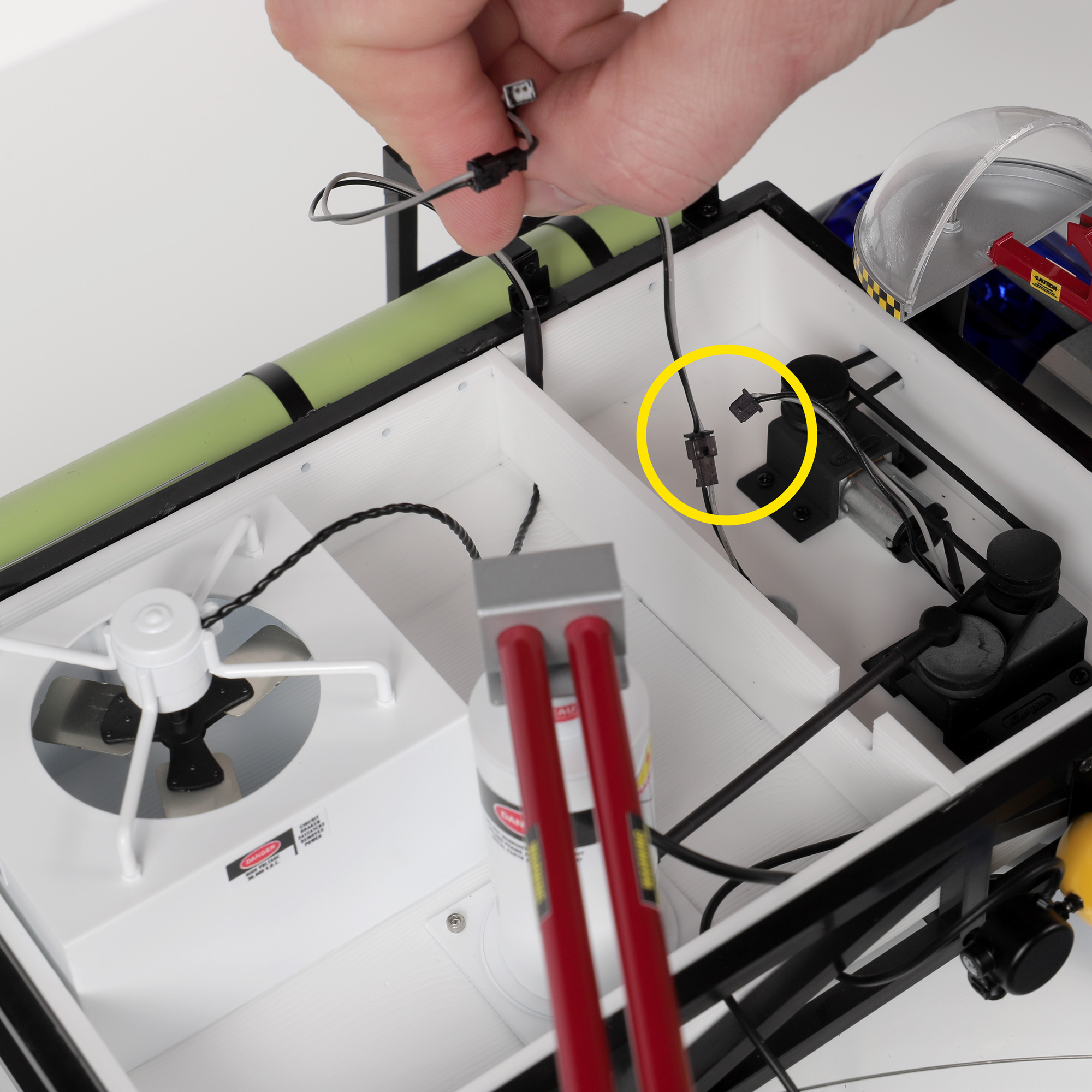
Disconnecting motor from the Y-splitter and connecting HVAC fan Y-splitter
  1. Disconnect the motor from the Y-splitter leading down into the hole in the roof box, and instead connect the end of the HVAC fan Y-splitter lead to it.
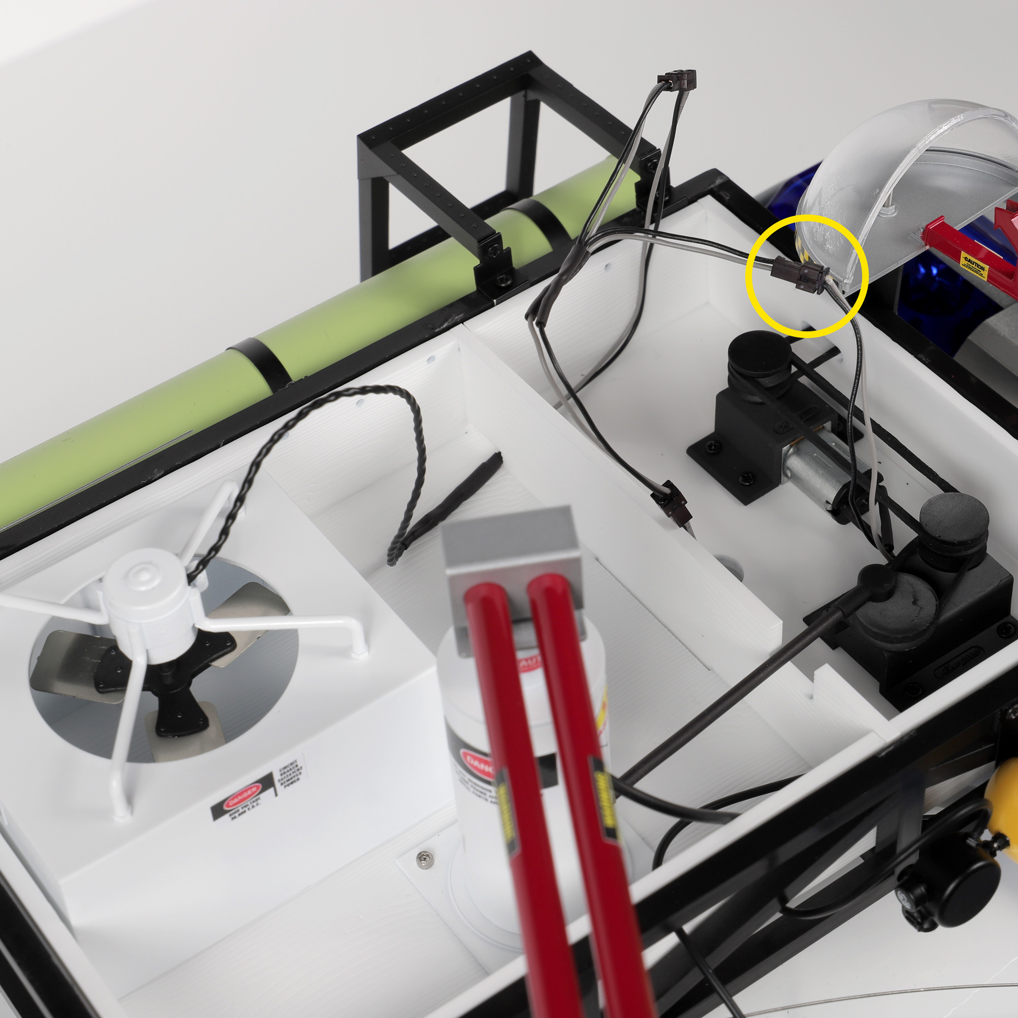
Reconnecting motor to the HVAC fan Y-splitter lead
  1. Reconnect the motor to the HVAC fan Y-splitter lead. The whole roof box is now powered from the models stock power. It is safe to power up the model if you wish to test everything.

Step 4 Detailing the Cross-section Sensitivity Unit

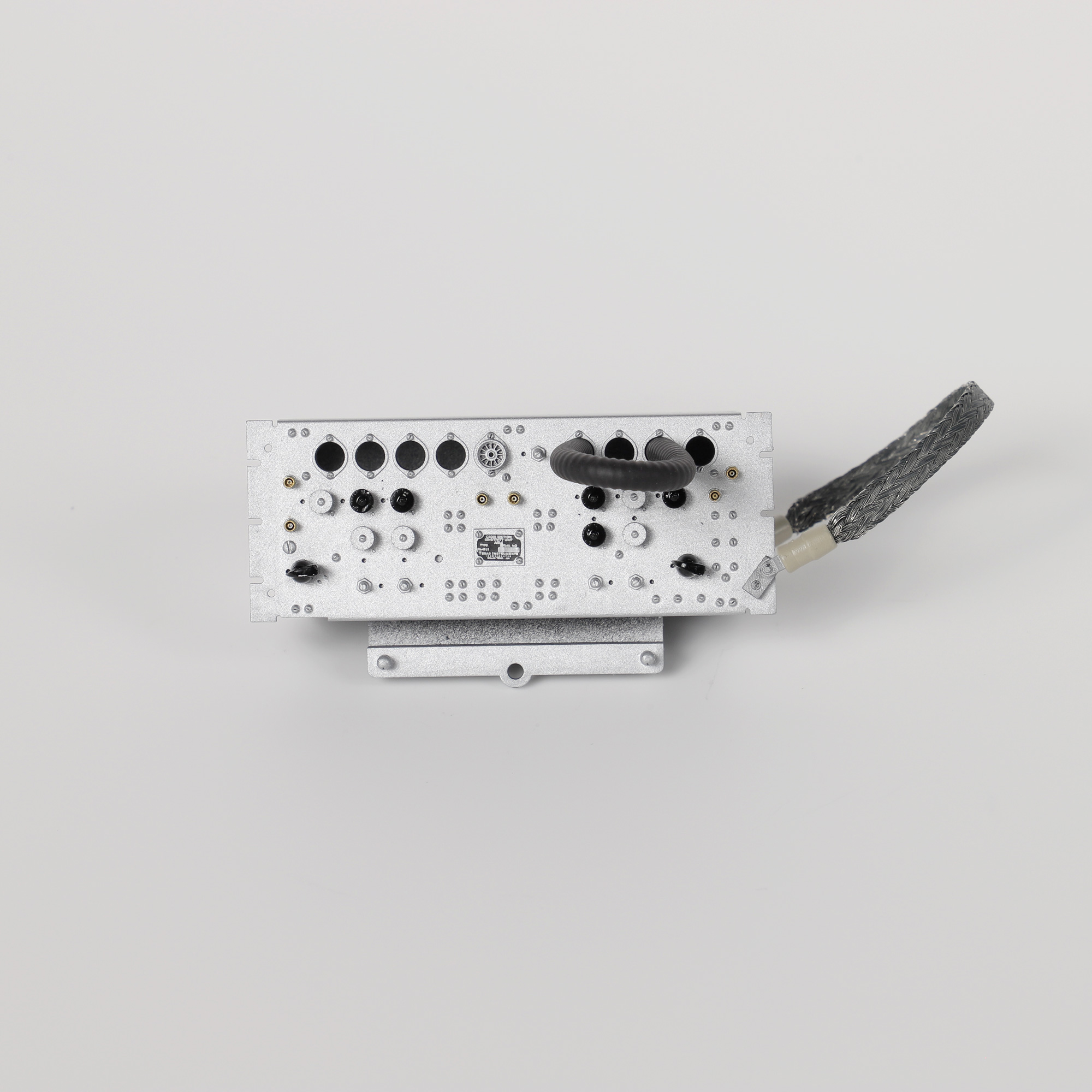
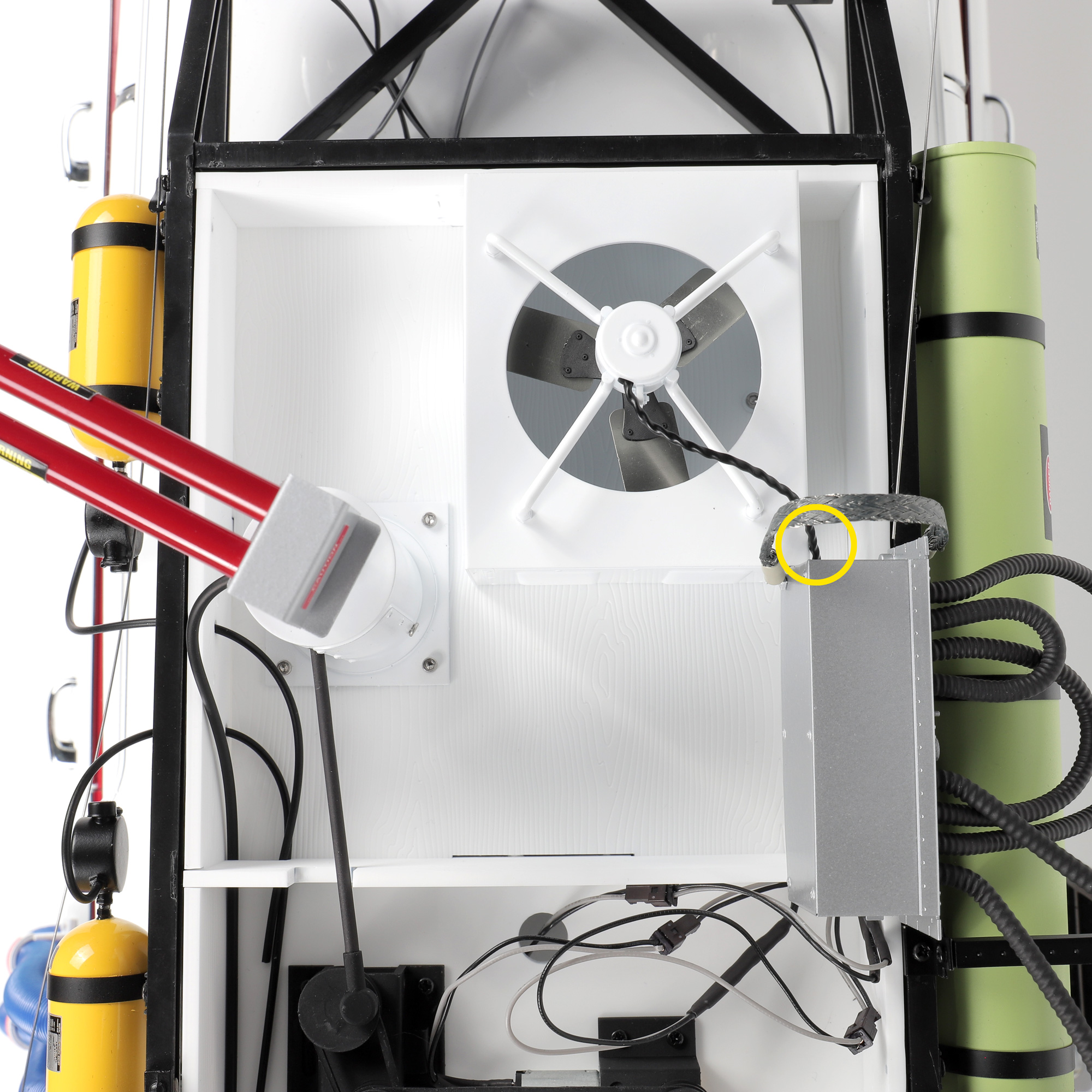
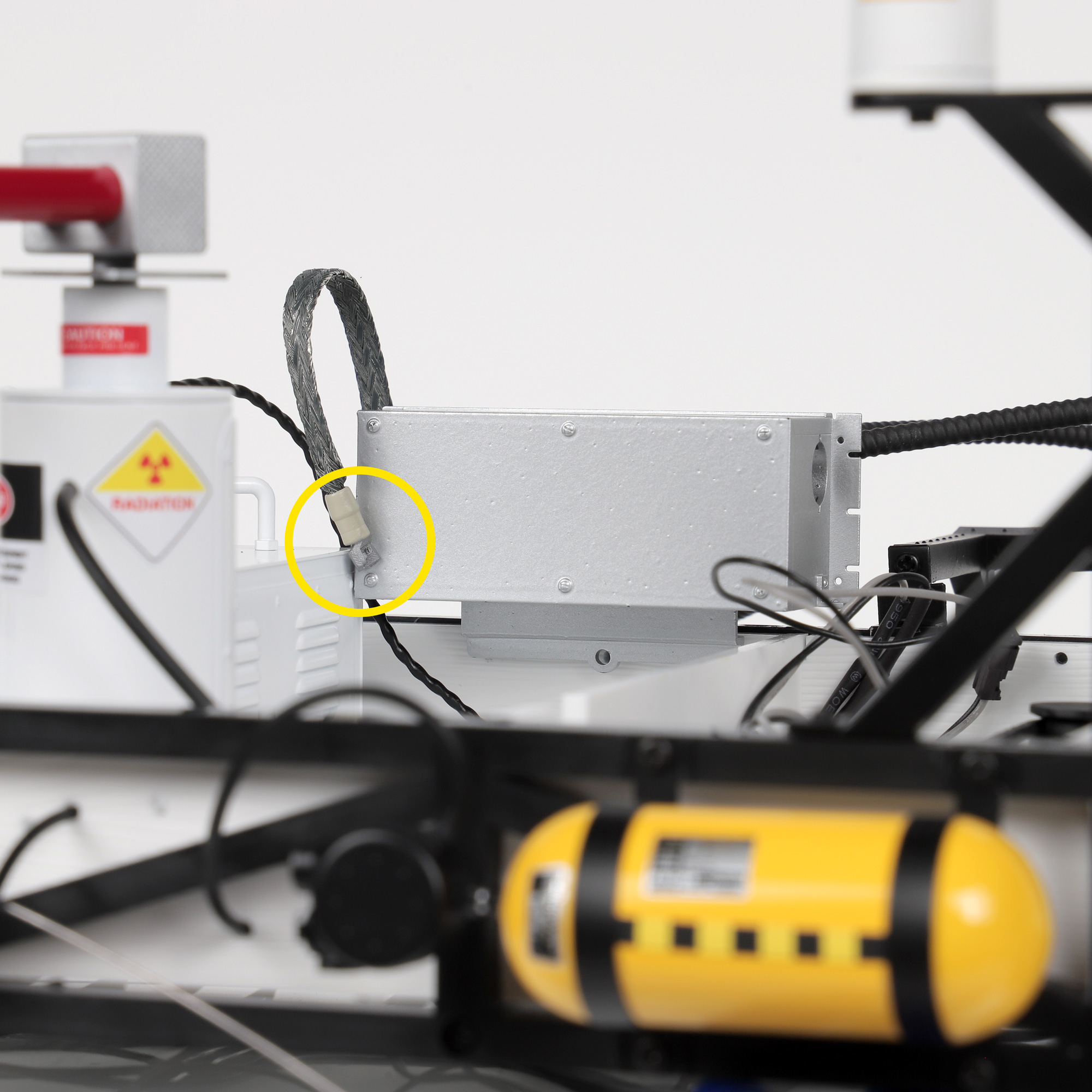
  1. FRAGILE PART – HANDLE WITH CARE! The earth cable has unique ends. Take each end and push fit into place. Please check the photos for correct placement. DO NOT GLUE these parts into place, they will require adjusting in later steps.
Correct placement on Cross-section Sensitivity Unit
Cross-section Sensitivity Unit - Fragile. Handle with care
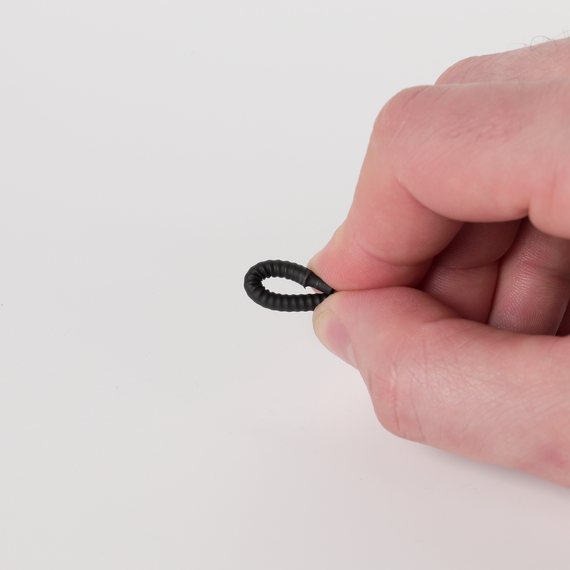
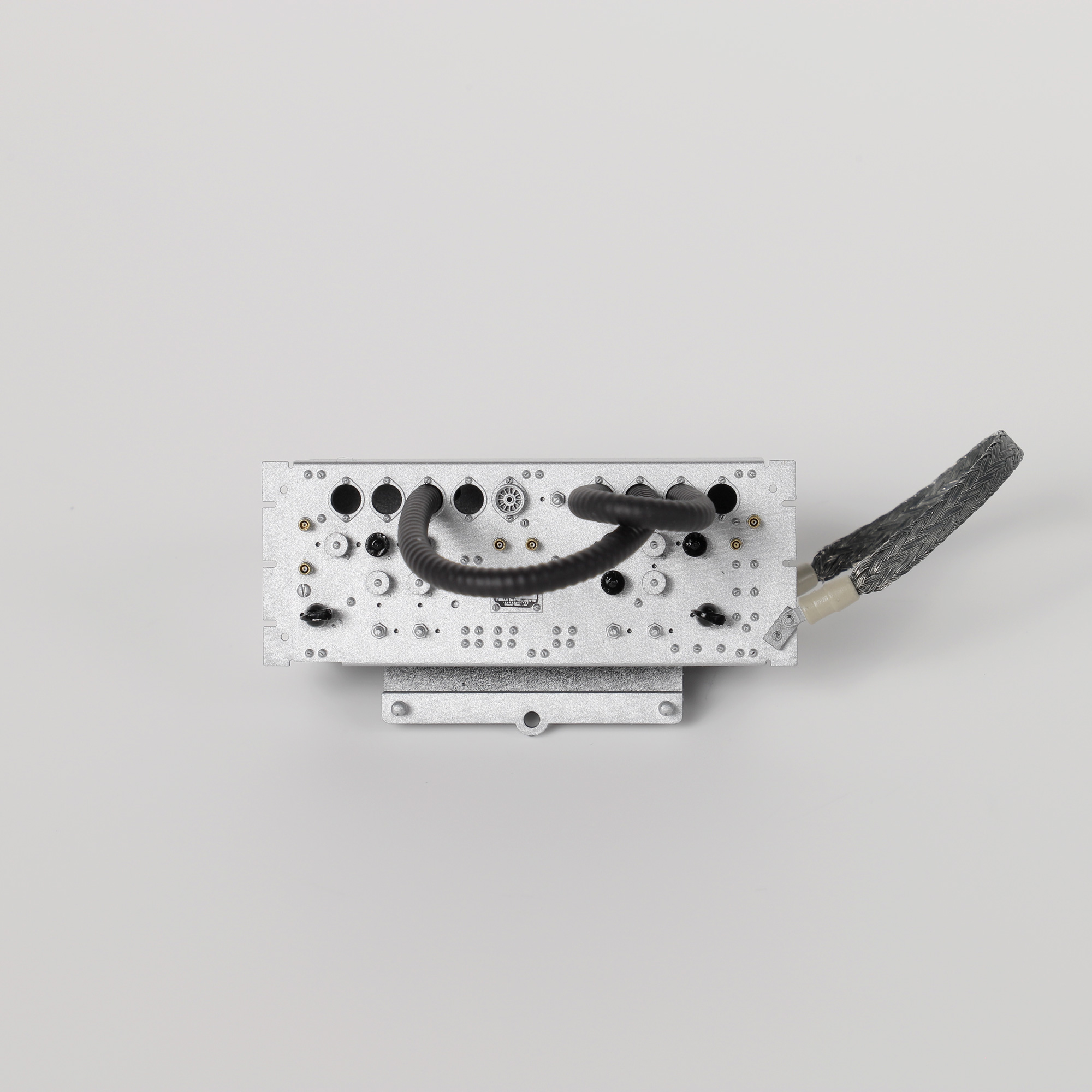
  1. Before adding the ribbed hoses, bend the ends tightly so that they have a bend on each end. This will allow the hoses to droop down from the cross-section sensitivity unit once inserted – looking more realistic. You can use your fingers to mould the shape of the hoses.
Bending ends of ribbed hose together
Ribbed hose after bending
Shortest length of ribbed hose inserted
  1. Lay all the ribbed hoses out and begin with the shortest length, we will work up to the longest hose through each step. Insert the shortest ribbed hose into the following holes. Twist slightly as you push for an easier fitment.
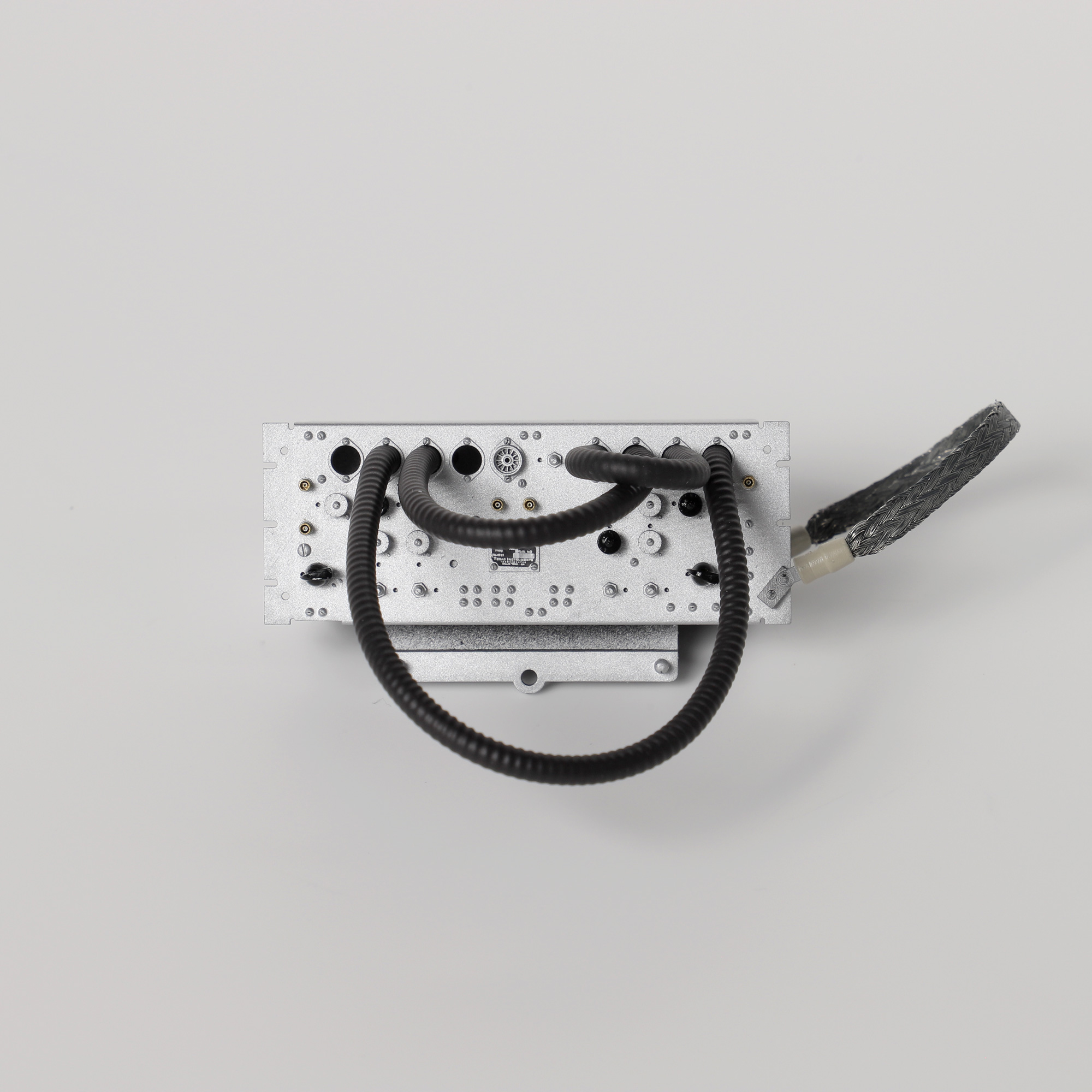
Fourth longest length of ribbed hose inserted
  1. Insert the next shortest length of hose into the following holes.
Third longest length of ribbed hose inserted
  1. Insert the next shortest length of hose into the following holes.
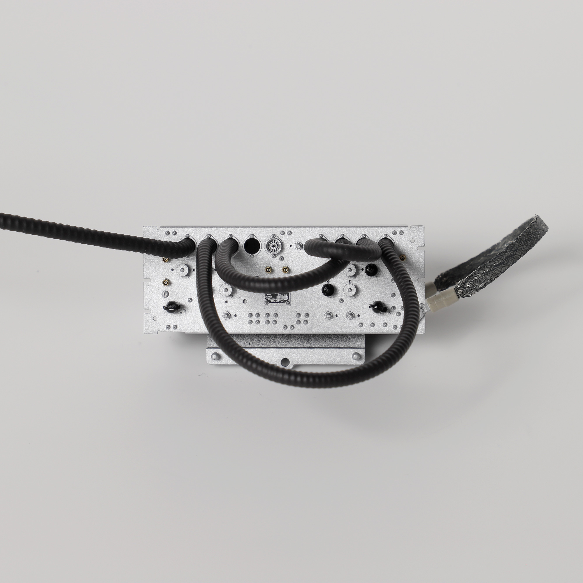
Second longest length of ribbed hose inserted
  1. Insert the next shortest length of hose into the far left hole.
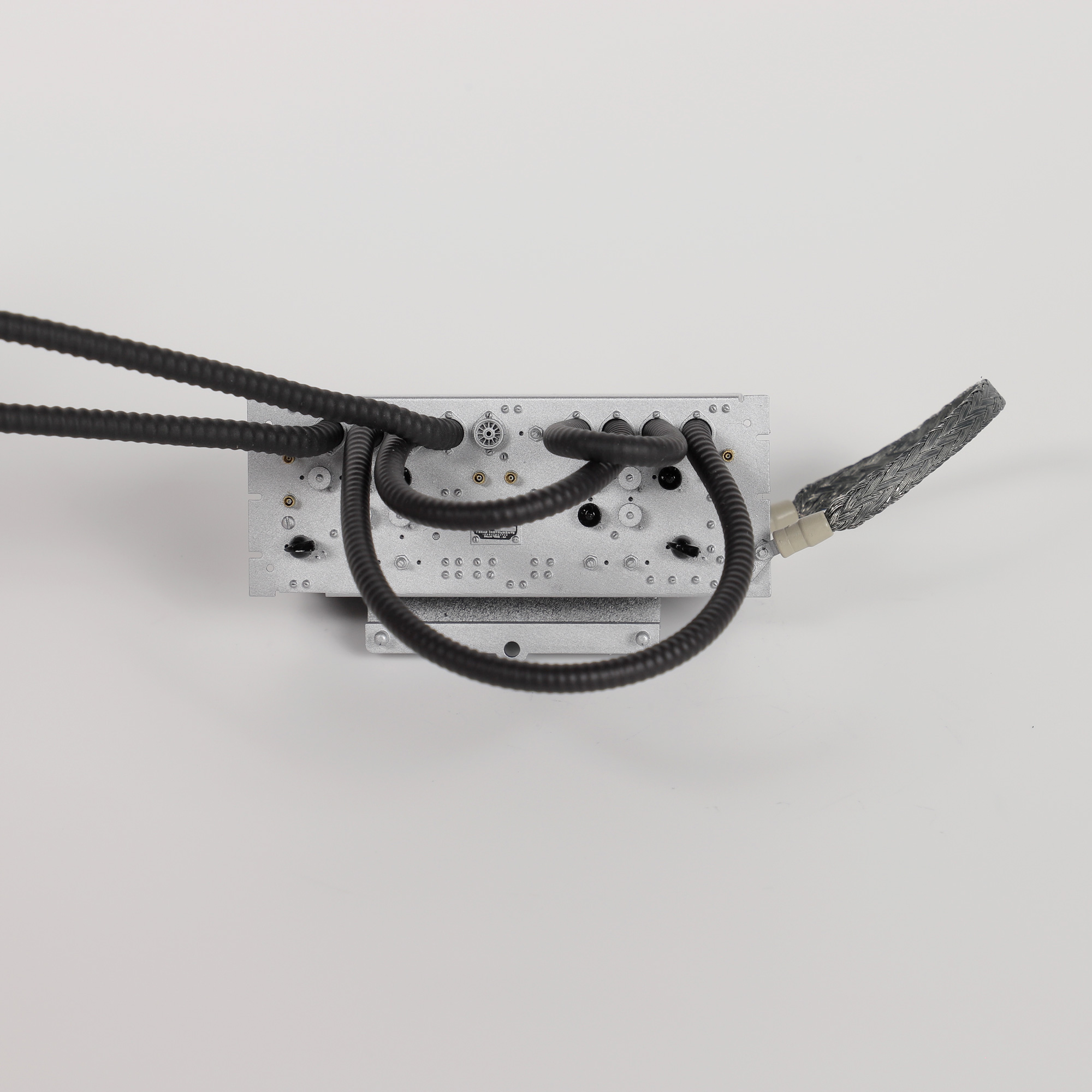
Longest length of ribbed hose inserted
  1. Insert the final, longest length of hose into the last remaining hole.

Step 5 Installing the Cross-section Sensitivity Unit

  1. Ensure the HVAC power cable is tucked in behind the cross-section sensitivity unit before installing. Push the two locator pins on the cross-section sensitivity unit into the side of the roof box to hold it in place. You may have to rotate the earth cable bracket slightly to avoid hitting the HVAC unit.
HVAC power cable tucked behind cross-section sensitivity unit
HVAC power cable tucked in position
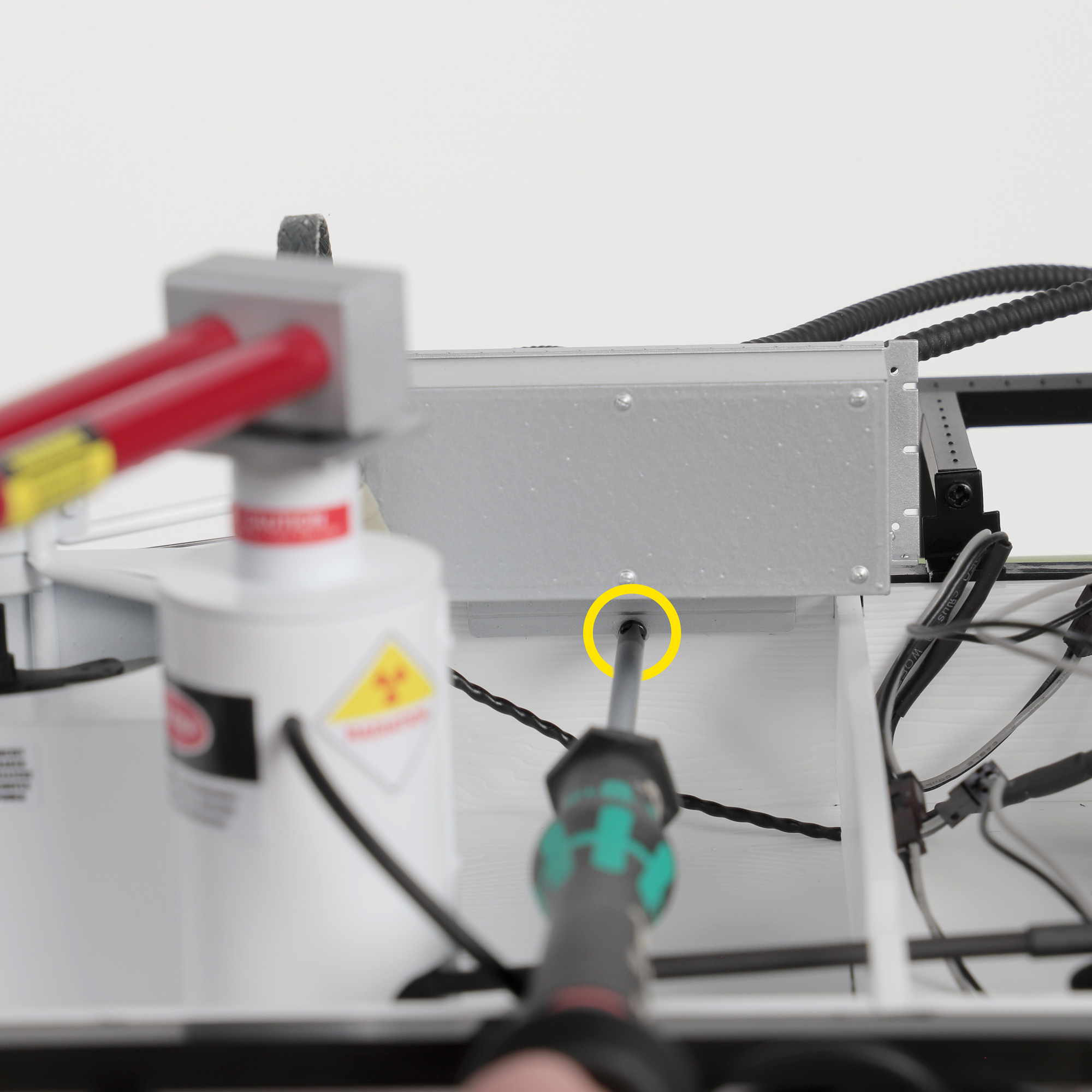
  1. Using a PH0 screwdriver, take 1 x ML1 screw and fit the cross-section sensitivity unit to the inside of the roof box. Be careful not to over tighten.
Fitting cross-section sensitivity unit to the inside of the roof box
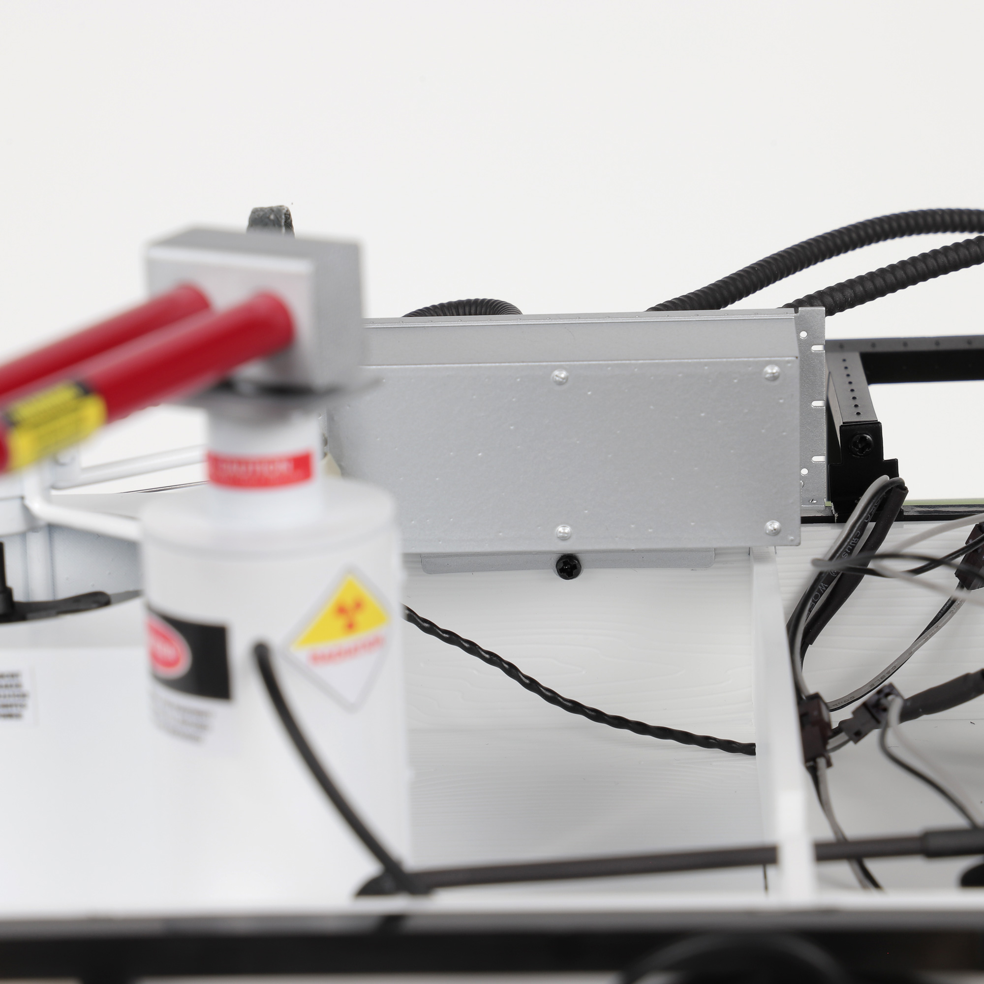
Cross-section sensitivity unit attached to inside of the roof box
Routing loose ribbed hoses from the cross-section sensitivity unit into the motor compartment.
  1. Loop and route the two longest, loose ribbed hoses from the cross-section sensitivity unit over and into the motor compartment.
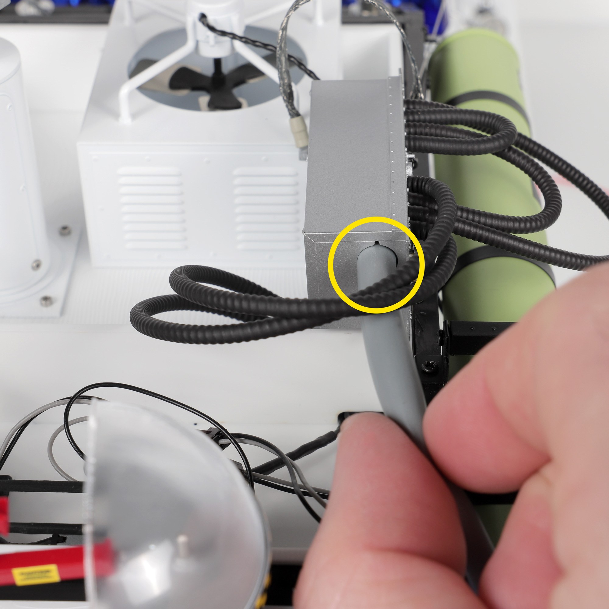
Feeding grey hose into cross-section sensitivity unit
  1. Feed the grey hose from KIT 2 into the side of the cross-section sensitivity unit.

Step 6 Installing the Front Heat Sinks and Ribbon Cable

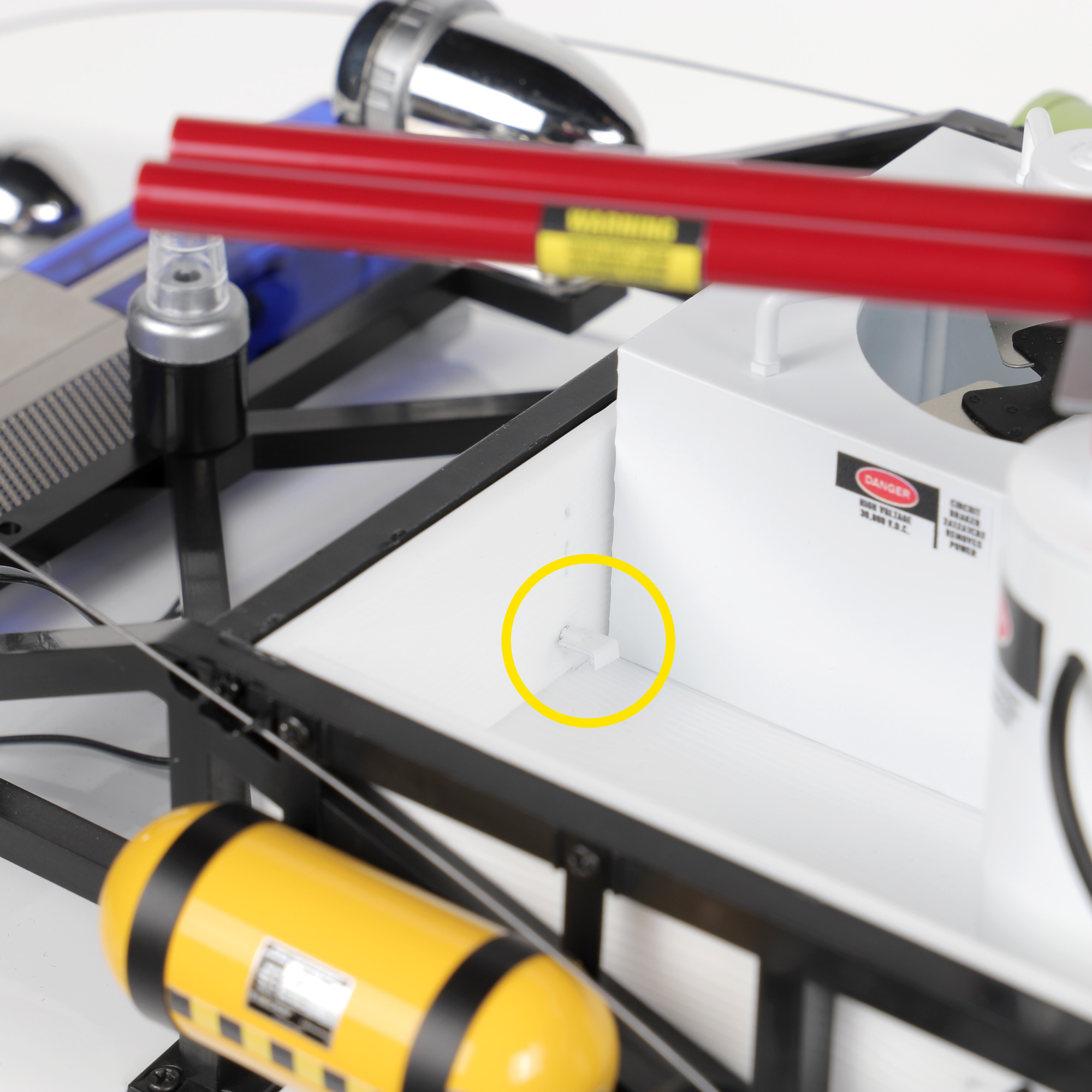
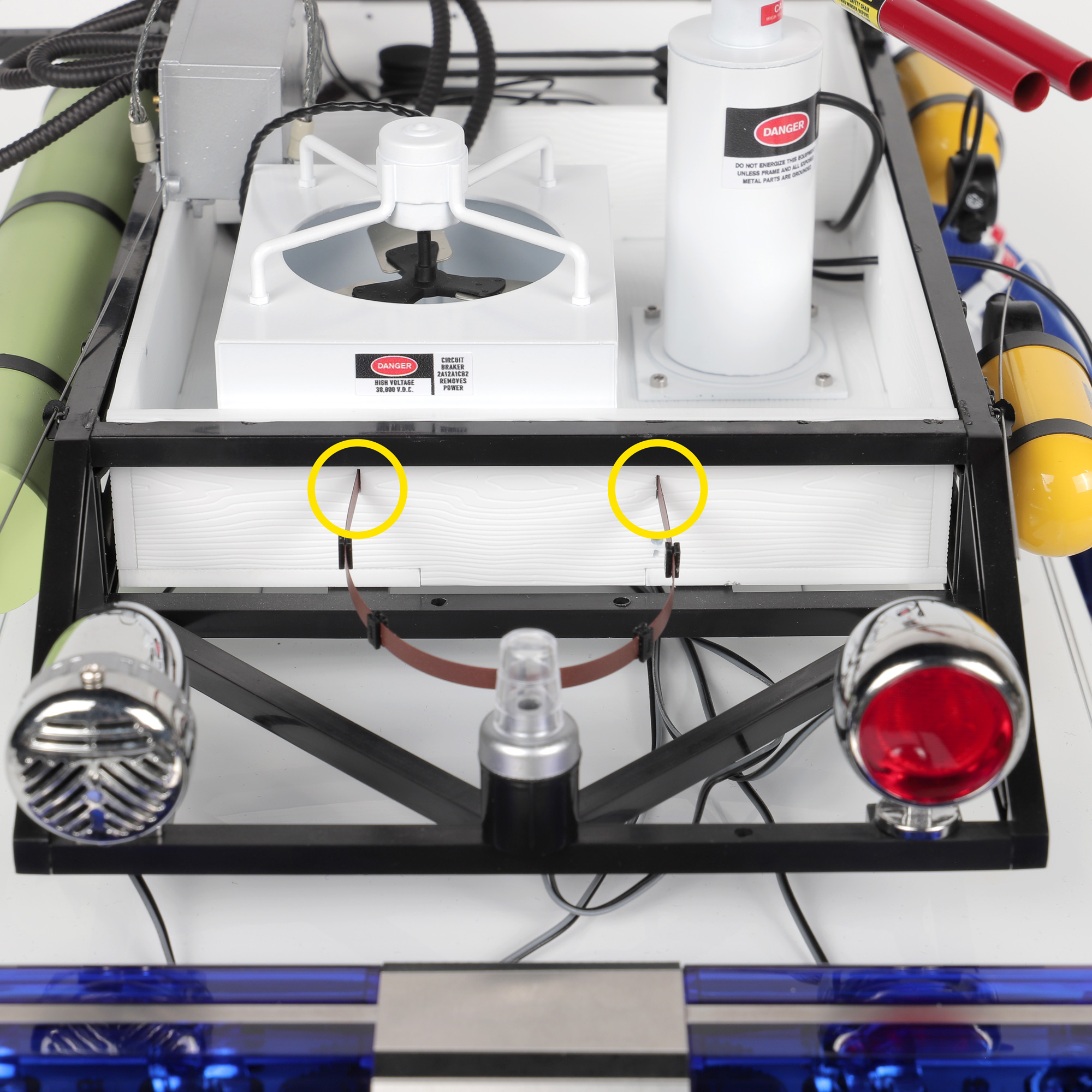
Inserting the ribbon retainer clip
  1. FRAGILE PART – HANDLE WITH CARE! Using a good set of tweezers, carefully insert the small ribbon retainer clip. This is a fragile part and care must be taken not to put too much force on it. If the pin feels tight when inserting into the side of the roof box, simply shave a small amount off with a craft knife for a better fit.
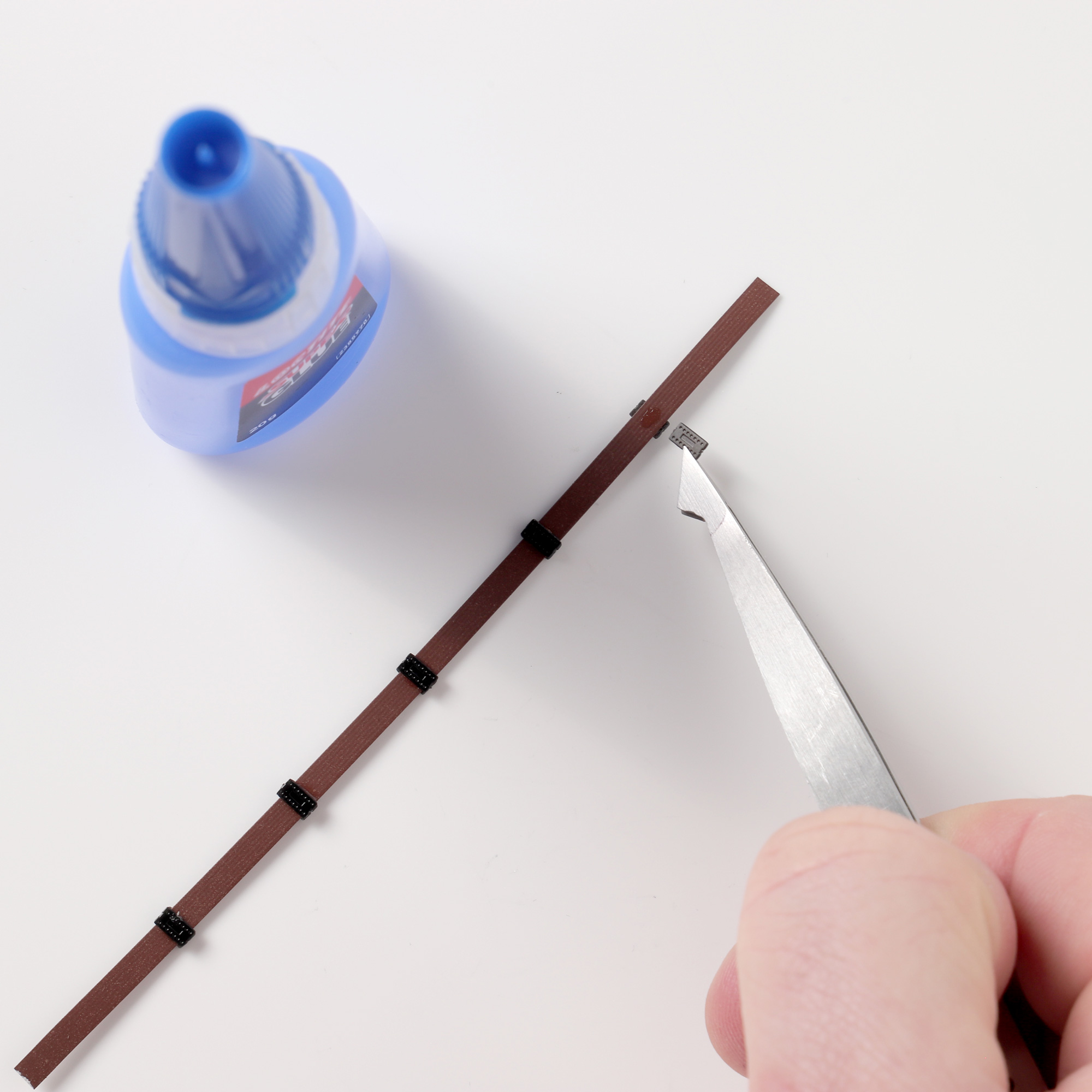
Gluing clips onto ribbon cable
  1. Snap the ribbon clips off the frame and use a tiny dot of Loctite Superglue to glue each into place, matching the photo. Five clips need to be glued on each side of the ribbon cable.
Ribbon cable ends inserted into roof box slots
  1. Install the ribbon cable into the front of the roof box by inserting the ends into each of the slots provided.
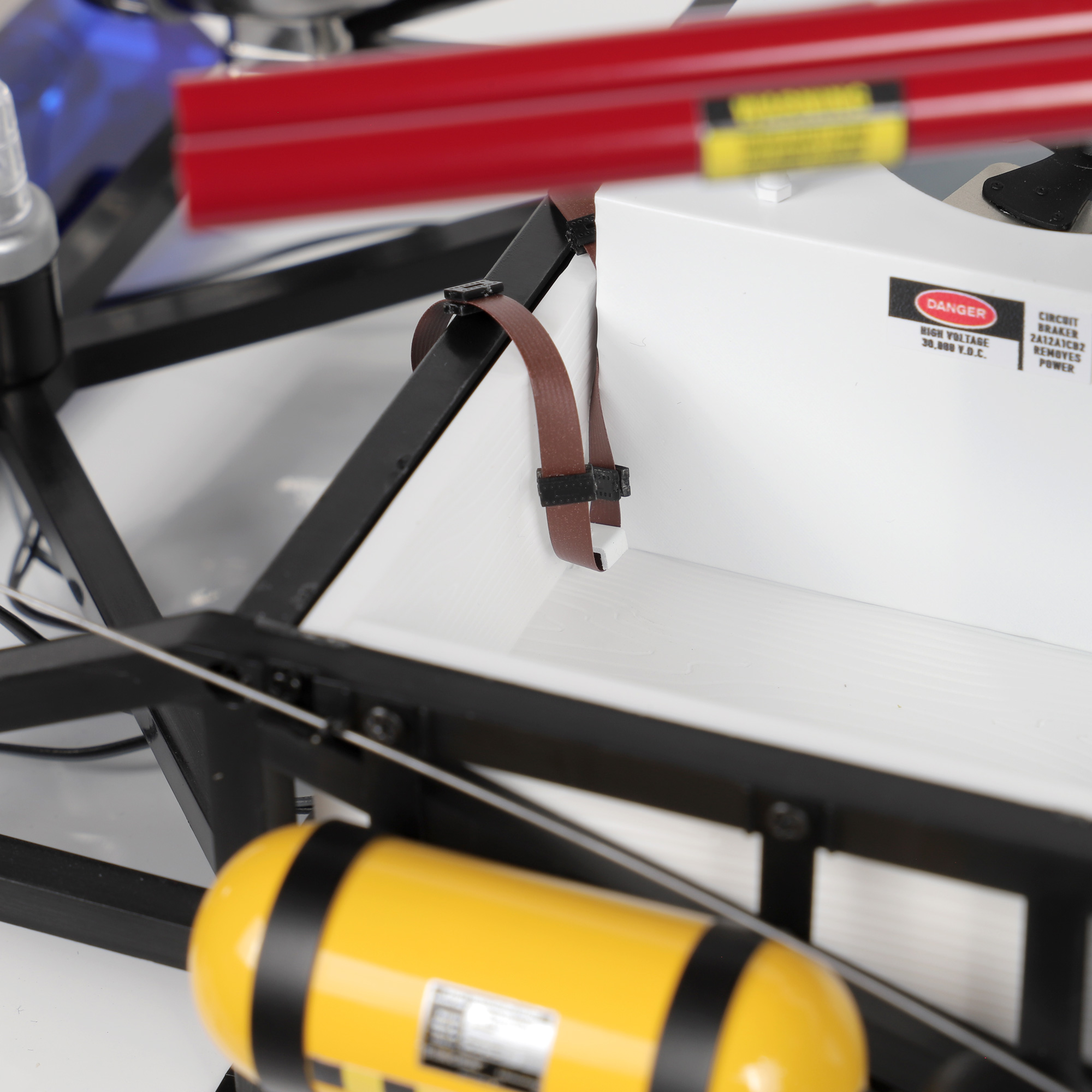
Ribbon cable bent into roof box
  1. Carefully bend the ribbon cable over and into the roof box, then under the retaining clip.
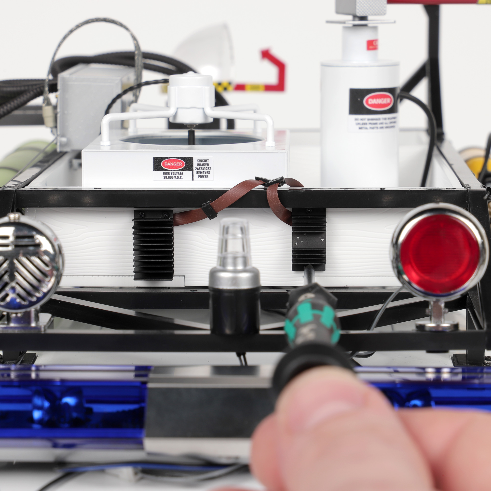
Screwing heat sinks to roof box
  1. Using a PH0 screwdriver, take 4 x ML7 screws and fit the heat sinks into the front of the roof box in the following positions. Be careful not to over tighten. The ribbon cable will be squashed flat behind each heat sink. You may wish to put a small dot of Loctite Superglue behind the left heatsink to keep it flat against the roof box.
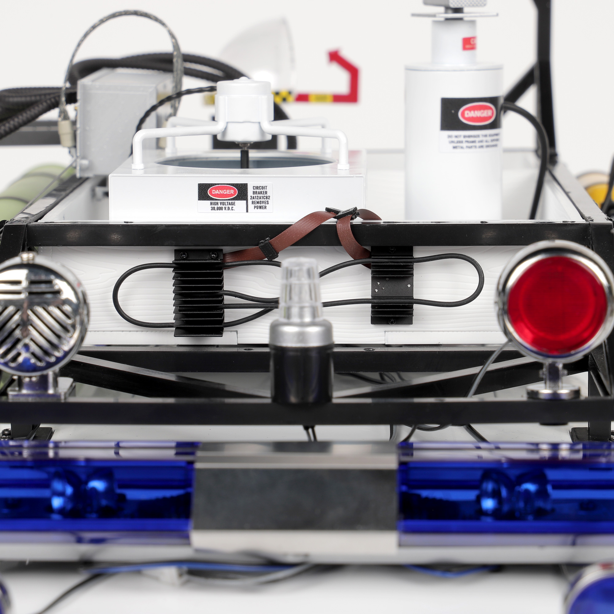
Rubber hose fed into heat sink fins
  1. Feed the thinnest rubber hose through the heat sink fins as demonstrated. Use a flat object to poke the hoses into the heatsinks – I found the flat end of a spudger tool to be the most effective.

Step 7 Detailing the Radome Antenna

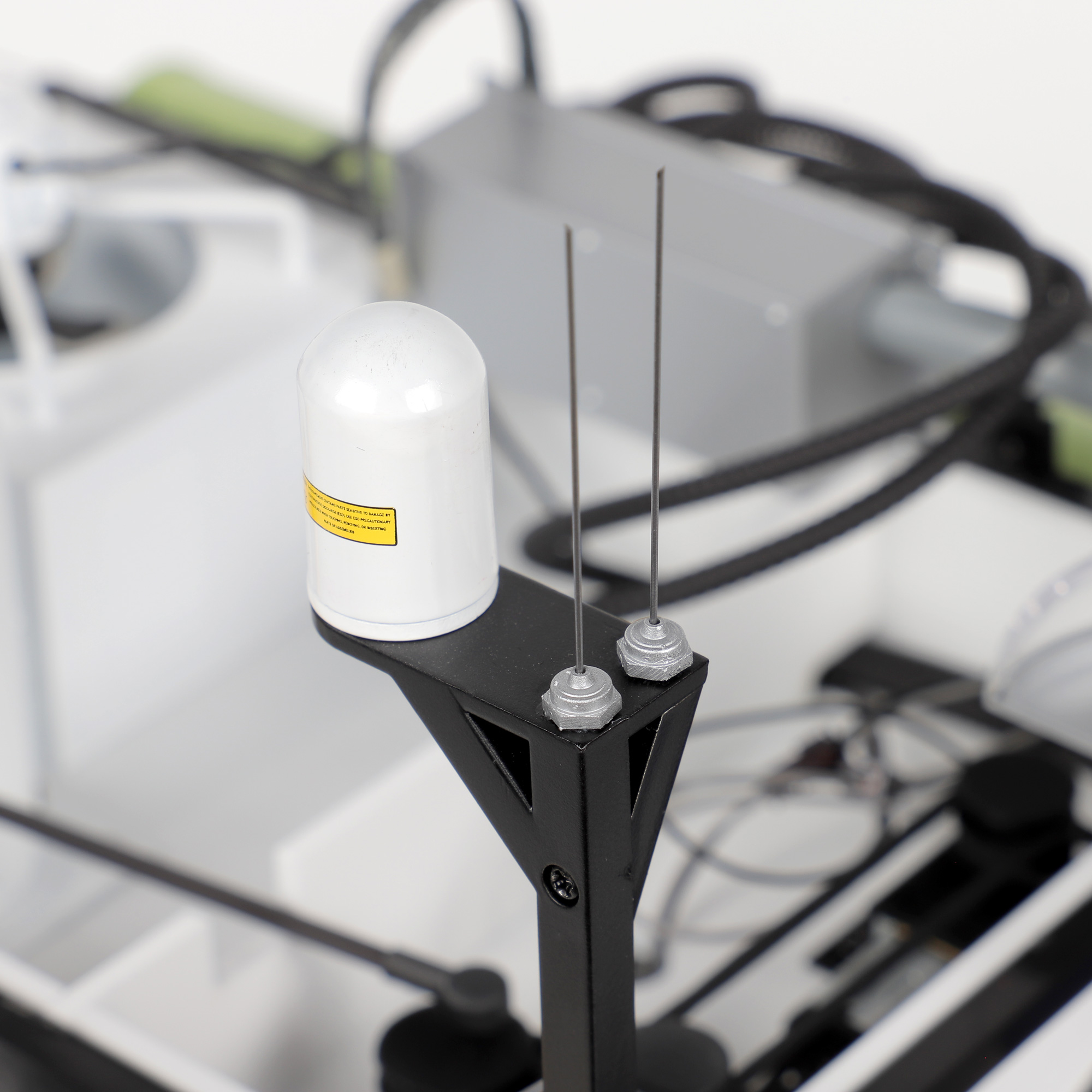
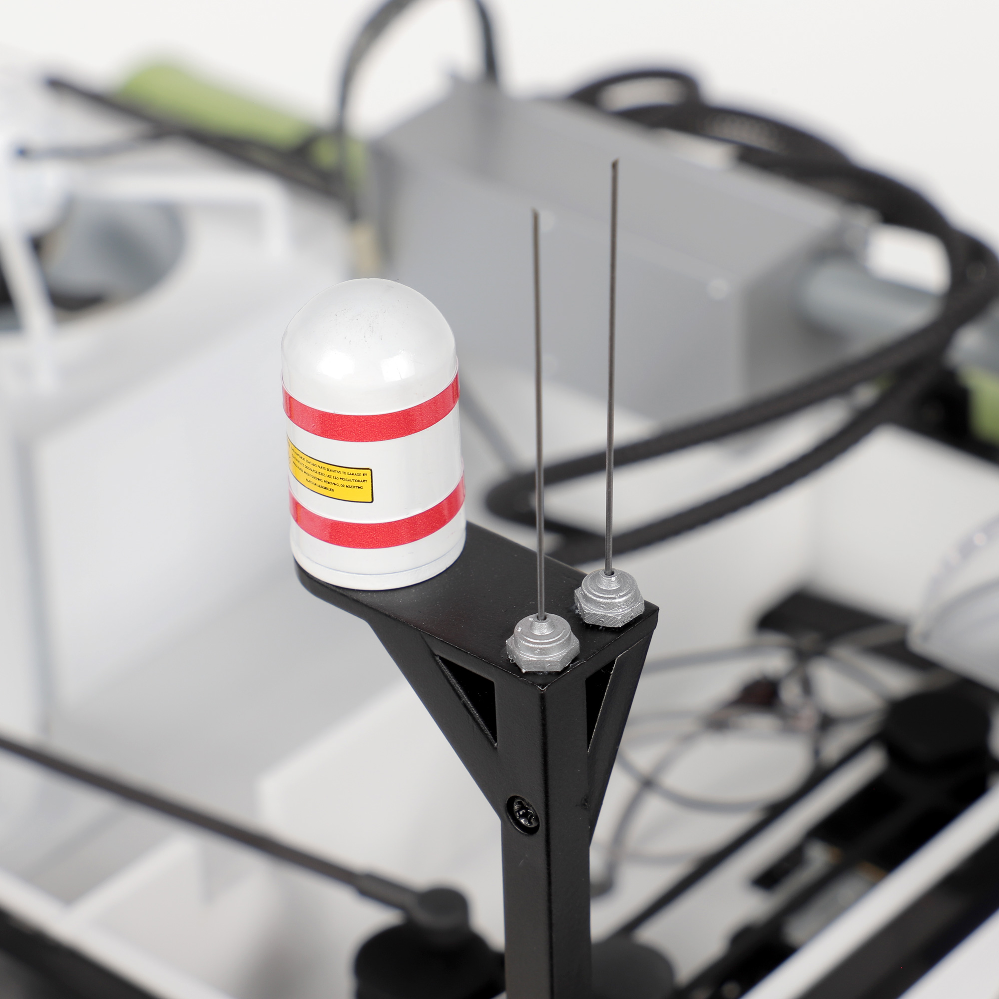
  1. Using a small dot of Loctite Superglue on the base of each antenna, glue them into place with the flat edges against the back of the fixing plate. Take two red sticker strips from the KIT 4 sticker sheet and apply in the locations shown.
Antennae glued onto fixing plate
Red sticker strips applied to antenna unit

Step 8 Inserting the Roof Box Lid

  1. To re-insert the roof box lid, first ensure the radar dish is pointing towards the back of the Ecto-1, then tuck the lid in beneath the cross-section sensitivity unit first. The lid will then fall into place nicely. To remove at a later date, follow these steps in reverse.
Arranging parts to lift roof box lid
Ecto-2 roof box lid in place

Final Step Adding the Final Detailing

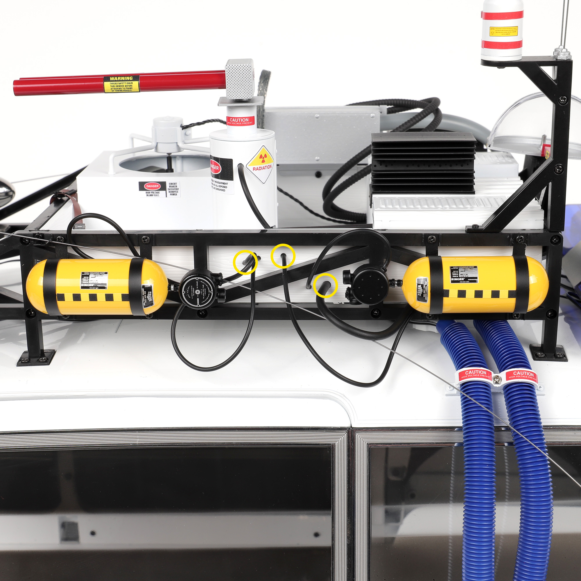
Feeding rubber hose into side of Ecto-1 roof box
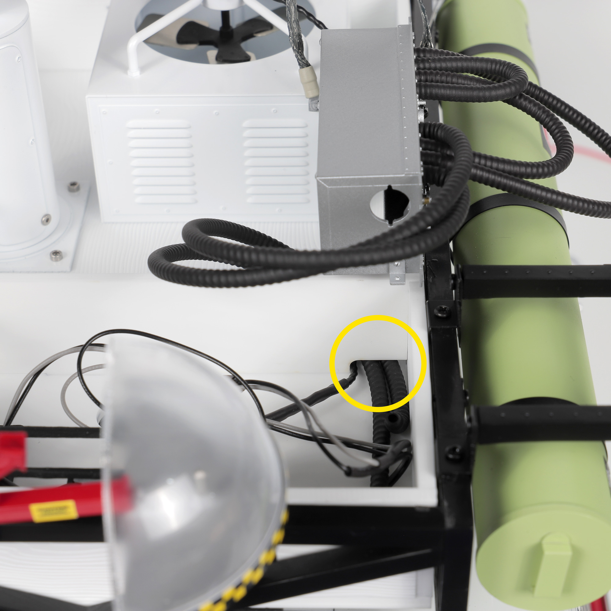
  1. To complete the side detailing, use the remaining two lengths of thin rubber hose and single length of thick rubber hose. Feed them through the holes in the side of the roof box and tuck the loose ends hanging outside the roof box in behind the Oxygen Tank brackets.
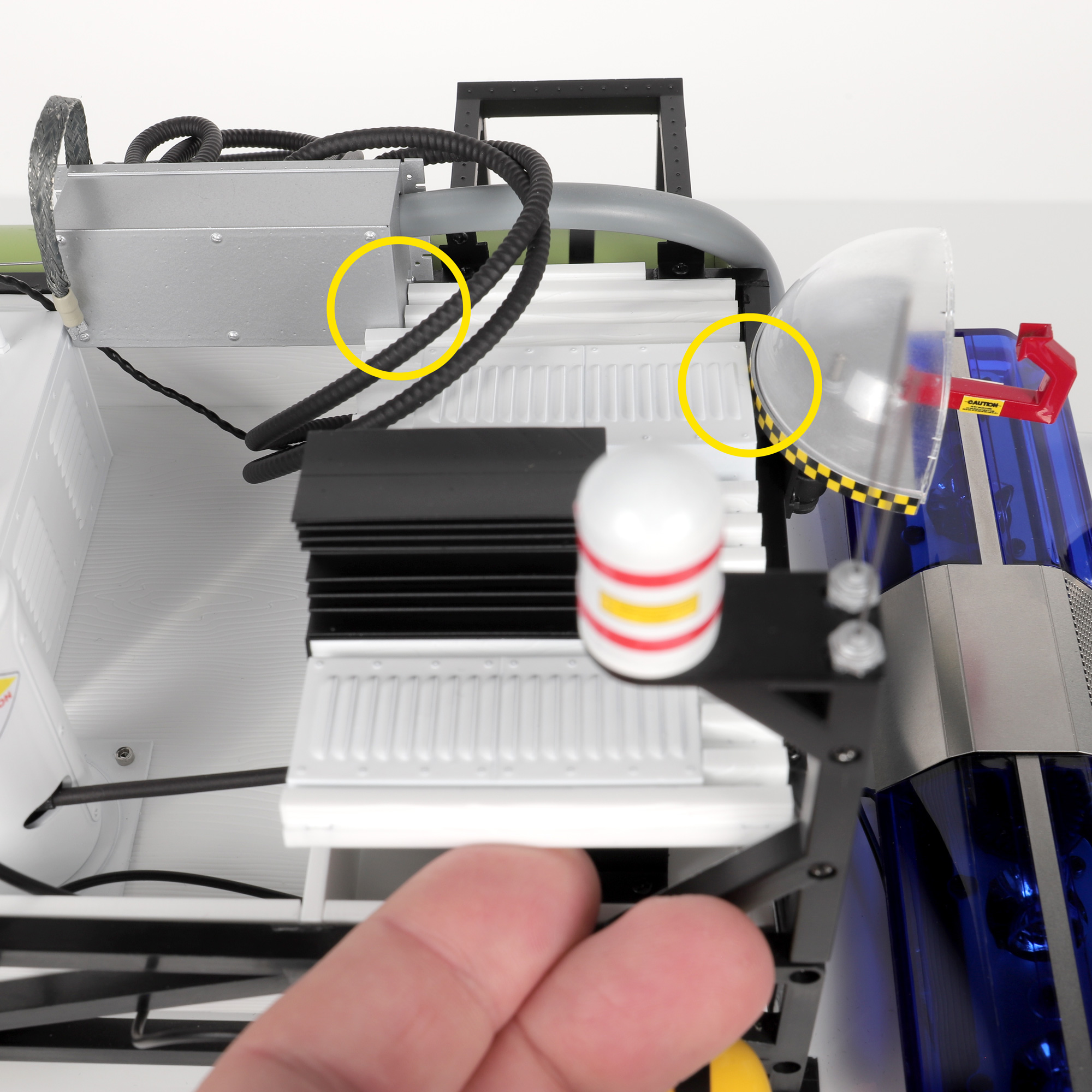
Detailing hoses fed into motor compartment
  1. Feed these last detailing hoses into the motor compartment.
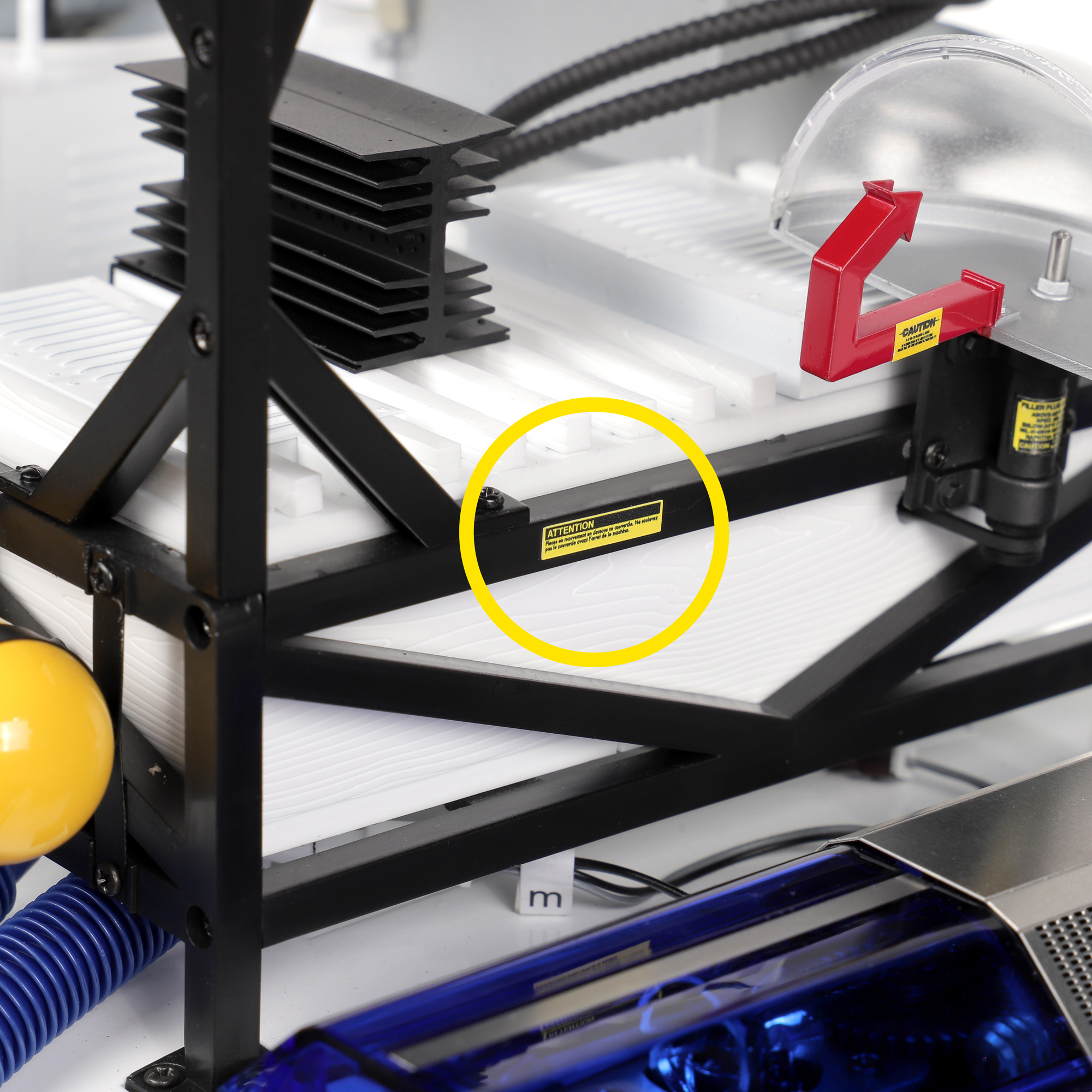
Kit 3 ‘ATTENTION’ sticker on Ecto-1 roof rack
  1. The final step to complete your Ecto-1 is to apply the ‘ATTENTION’ sticker to the roof rack from the KIT 3 sticker sheet (number 07).

Your Ecto-1 is now Complete! 🎉

Thank you for joining us on this journey to complete your Ecto-1 in style.
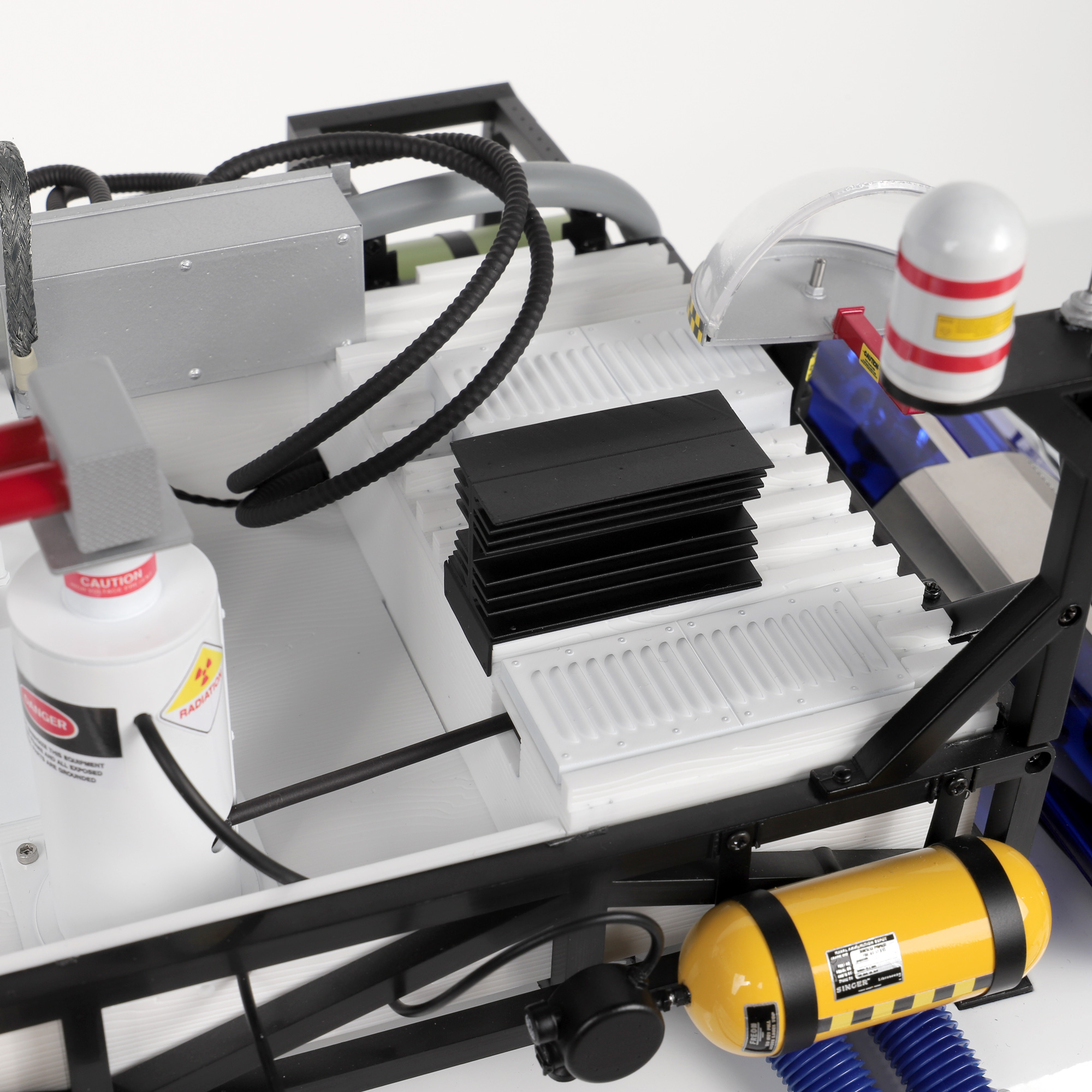
Here at Mike Lane Mods, we hope you enjoy your upgrades and completed model!