Installing the

Ultimate Scanner

Installing the Ultimate Scanner

Designed for the Build the K2000 Knight Rider KITT from Fanhome/DeAgostini/Altaya. 
  Please take the time to read and follow these instructions carefully.

Failure to do so may result in damaging the model, the electronics, the mod itself, may cause the device to behave unexpectedly and may void its warranty.

This modification contains sensitive electronics. To avoid static shock which could damage the electronics, please ensure you handle with care, avoid touching the metal parts and avoid placing on or near static surfaces whenever possible.

Preparing the front bumper

Preparing the front bumper

Removing screws connecting the front of wing to back of front bumper
The scanner is designed to replace the stock scanner and mount to the original bracket.

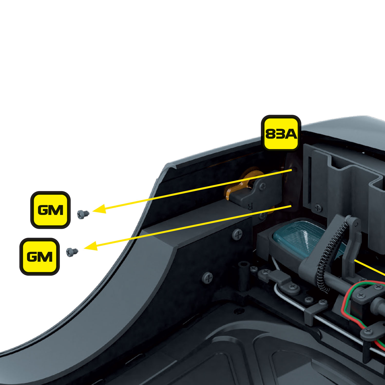
If you have completed Stage 86, and if you haven’t already done so in the previous step, remove the 2 x GM screws on each side that connect the front bumper to the front wings.

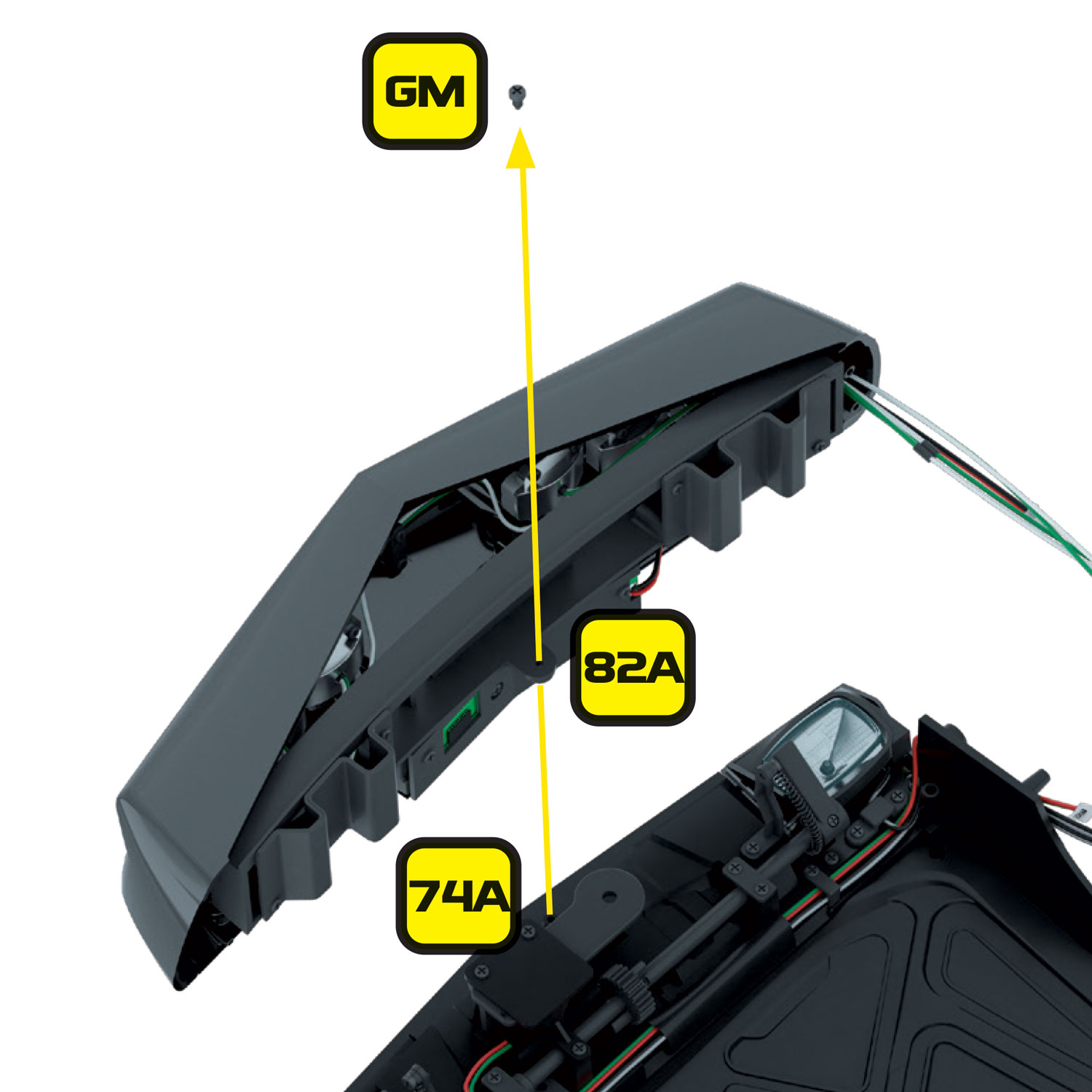
Then remove the 1 x GM screw from the centre of the front bumper that connects to the front engine bay frame (74A).

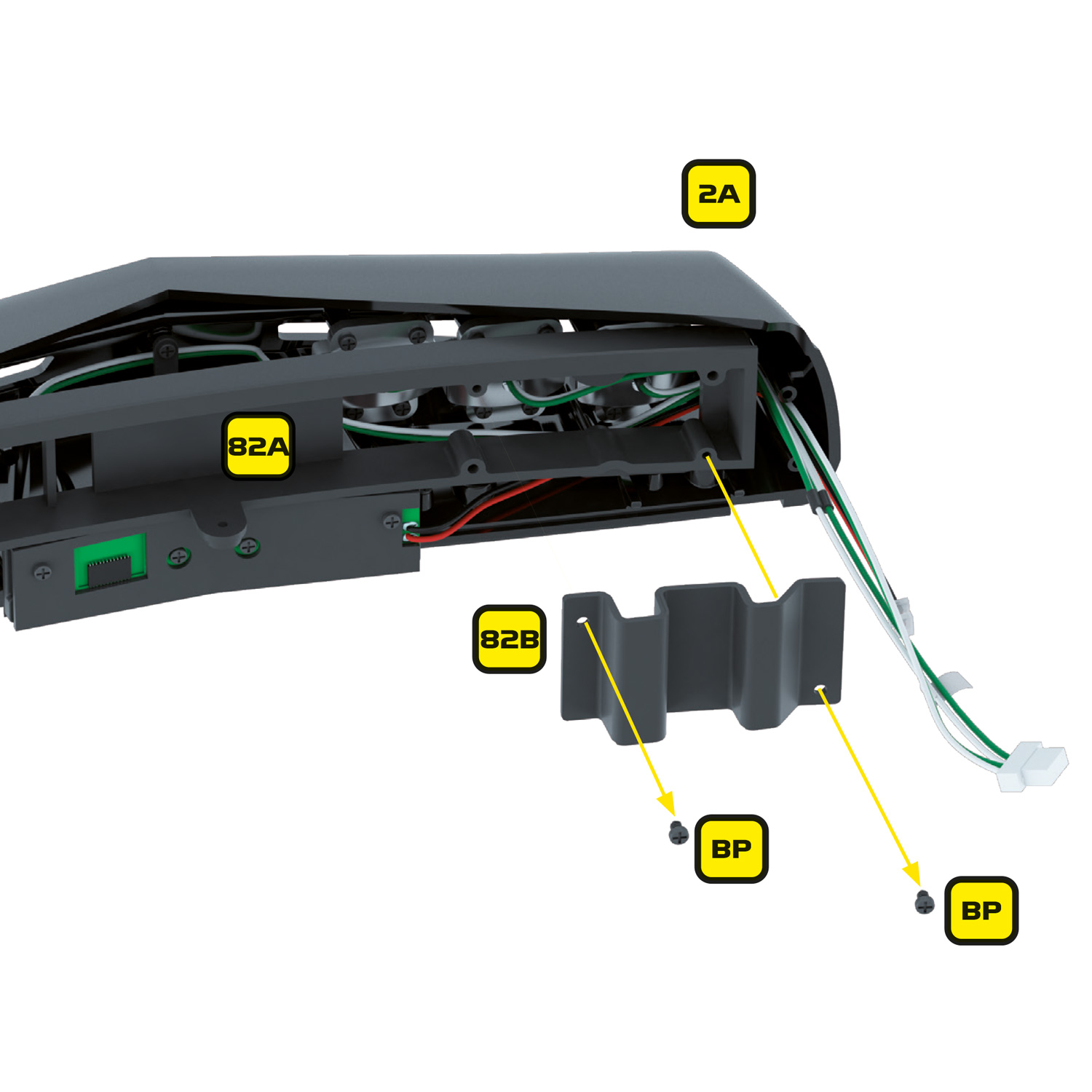
If you have already completed Stage 82, you will need to remove the left and right bumper brackets (82B) and (82C).

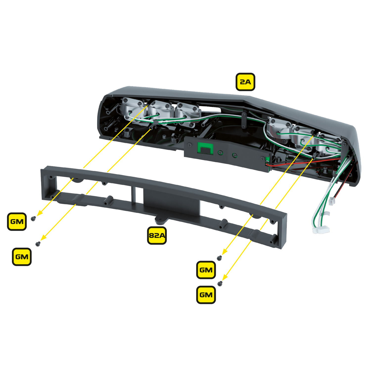
Next remove the inner frame (82A). Set these parts and their associated screws aside for refitting later.

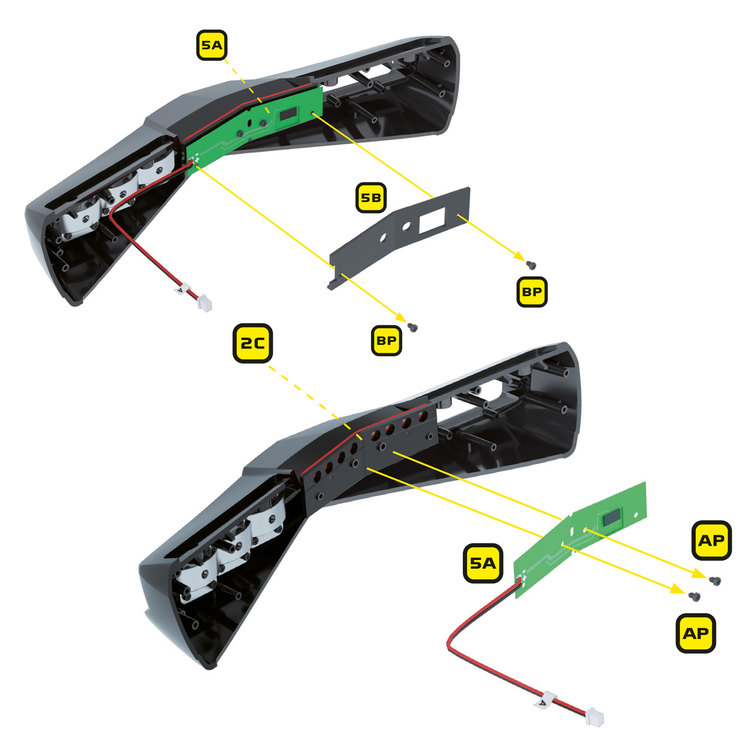
Remove the 2 x BP screws holding the inner case of the scanner (5B) in place. Next remove the stock scanner circuit board by removing the 2 x AP screws holding it in place. Except for the scanner which will no longer be needed, keep all of these parts and screws safe as they will be re-used for the Mike Lane scanner.

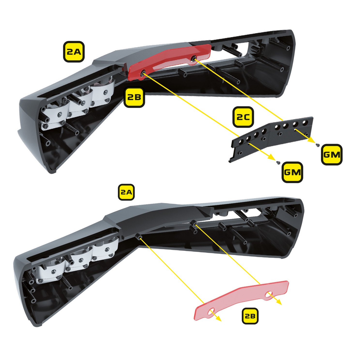
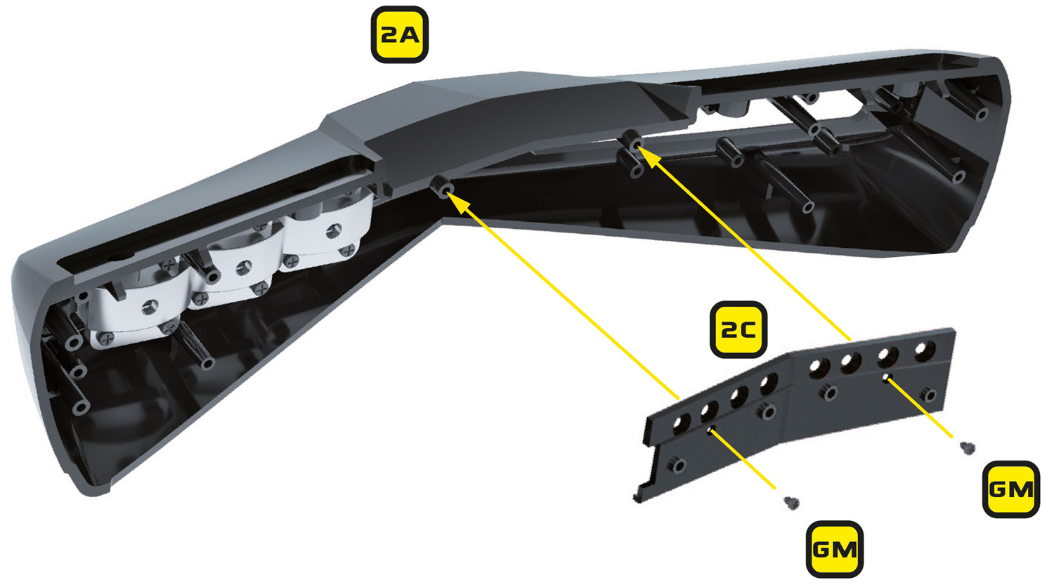
Remove the scanner base (2C) and scanner lens (2B) from the front bumper. The lens will no longer be required but the scanner base will be re-used.

The front bumper is now ready to take the new Mike Lane scanner.

Installing the Ultimate Scanner

Installing the Ultimate Scanner

Install the scanner base (2C from stage 02) back into the bumper, but without the red scanner lens. The new interchangeable lenses will be added last.

Now take the small scanner cable and connect into the scanner socket so that the grey cable is towards the TOP.  

FRAGILE CABLE: When handling the small scanner cable, take care not to pull on the wires. This is a fragile component and may break if not handled with care. If you need to remove the cable from the scanner socket, grip and pull by the plug of the cable – do not try to remove by pulling on the cable itself! A spare is included within the kit if required.

Take the ultimate scanner circuit board and install it into the scanner base (2C) using two AP screws – essentially following the same installation instructions from stage 05. The socket on the back of the new scanner should be on the right side of the circuit board. 

Place the scanner inner case (5B from stage 05) over the top of the scanner board, feeding the cable through the hole so that the socket is visible through the opening. Screw the scanner inner case back on using the original 2 x BP screws.

Connect the other end of the small scanner cable to the Mini Alpha controller socket labelled SCANNER taking note that the grey cable is at the BOTTOM and also connect the supplied power cable to the socket labelled IN, with the grey cable at the TOP.

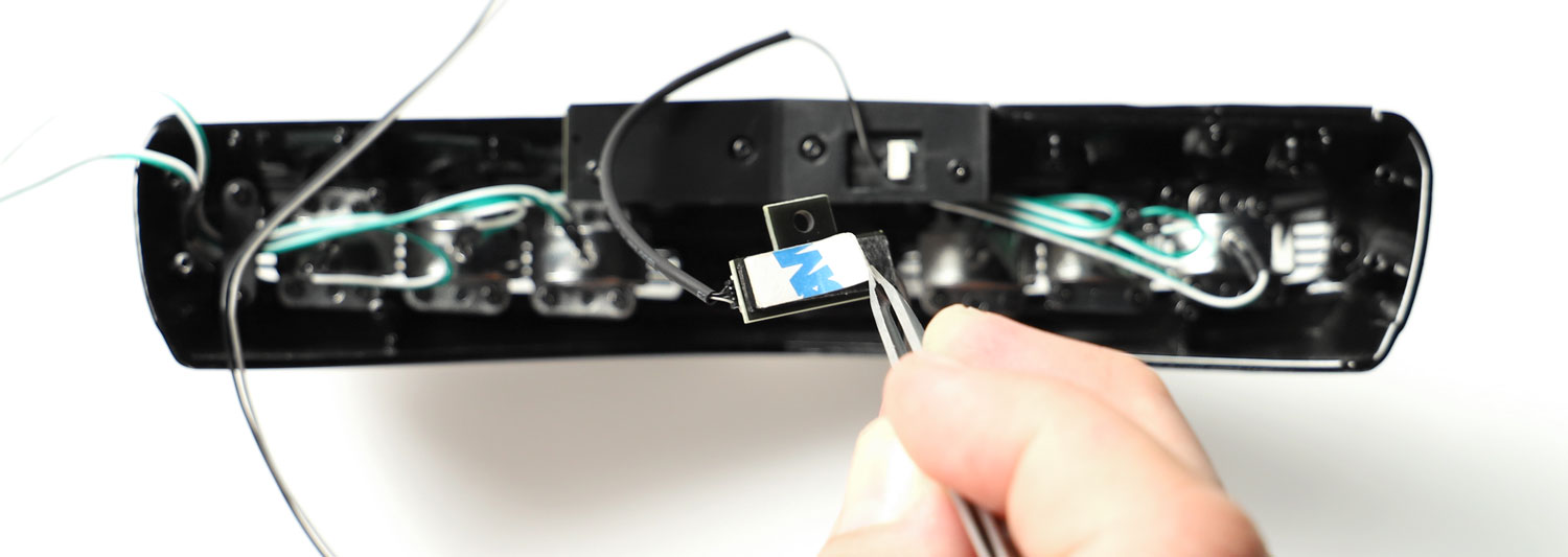
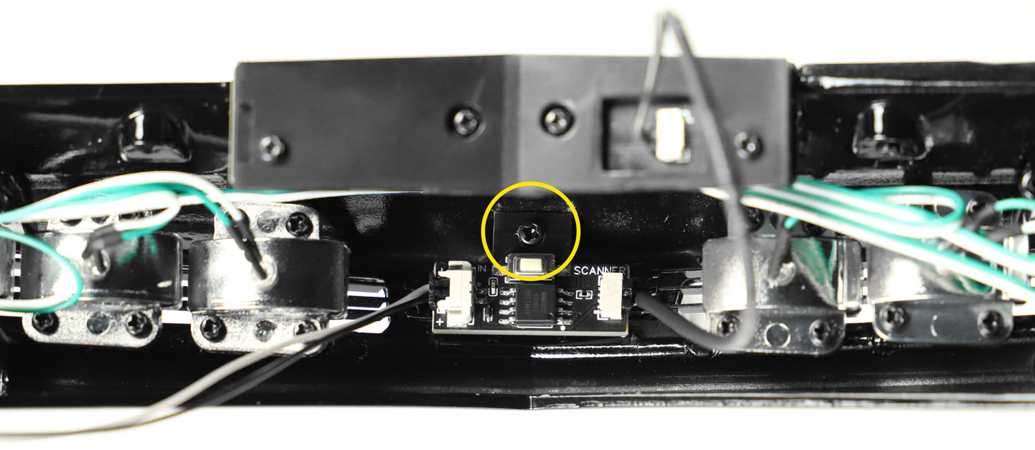
Now secure the Mini Alpha controller in place by first removing the 3M backing. Align the hole in the top of the Mini Alpha controller with the top hole in the bumper. The Mini Alpha controller fits in the two holes which would otherwise be used by the small cable grip (part 82D) in issue 82. This part is no longer needed and won’t be used.

Using one of the supplied screws within the Mike Lane Ultimate Scanner kit, secure the Mini Alpha controller into place.

Remove the driver side fender by unscrewing the 2 x EM screws at the front and the 2 x VM screws on the rear as shown. Route the scanner power cable over the wheel arch with the existing cables and connect to the stock scanner cable labelled ‘A’.

Carefully refit the driver side fender taking care not to crush any of the cables.

Now refit the inner frame (82A) and left and right bumper brackets (82B) and (82C) and refit the nose to the car.

Next, to use the interchangeable lenses, simply insert the bent clear lens first, then the flat coloured lens you would like to use (red for KITT or yellow for KARR) in behind the clear lens. The lenses can then be easily inserted and removed without the need to remove any screws.

Button functions:

The mode button on the Mini Alpha controller can be easily accessed by reaching under the front nose.

Pressing the button will cycle through the following modes in this order:

  1. KITT Idle mode (standard scan pattern)
  2. KITT Cruise mode (faster scan pattern)
  3. KITT Surveillance mode (fastest scan pattern)
  4. KITT Hacked mode
  5. KITT Presentation mode – cycles between all effects in KITT mode with a 20 second delay between
  6. KARR Idle mode (standard scan pattern)
  7. KARR Cruise mode (faster scan pattern)
  8. KARR Surveillance mode (fastest scan pattern)
  9. KARR Hacked mode
  10. KARR Presentation mode – cycles between all effects in KARR mode with a 20 second delay between

When powering off KITT, the last used mode will be stored in the Mini Alpha’s memory and will be used when the model is next powered on.

  The installation is now complete!